background image

12

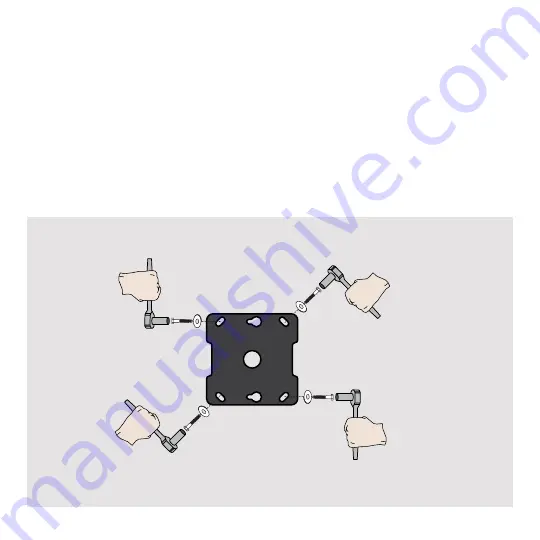
3.  Attach ceiling mounting plate


Align the mounting plate with the pre-drilled holes. Ensure that the cable pass through holes on the 
mount are positioned appropriately. 

Wood Joist/Truss Mounting:


Align the bracket with the screw keyed slots 
and turn to hold in place. Finish tightening all 
lag screws with washers until they are snug with 
the mounting surface. Do not over tighten the 
lag screws. Tighten the lag screws only until the 

washers are pulled firmly against the bracket.

Concrete: 

Align the bracket with the pre-drilled holes. 

Attach bracket to the ceiling using the six lag 
screws and six flat washers. Tighten all lag screws 

using a socket wrench and ½” socket.  Make sure 

the anchor is seated completely flush with the 

concrete surface even if there is another layer of 
material, such as drywall. Do not over tighten the 
lag screws. Tighten the lag screws only until the 

washers are pulled firmly against the bracket. 

Summary of Contents for LC-1

Page 1: ...OUTDOOR TV CEILING MOUNT INSTALLATION GUIDE Model Numbers SC 1 LC 1 WARRANTY REGISTRATION REGISTER FOR EXTRA BENEFITS Activate within 30 days of purchase seura com activate 5 13 4 1 8 4 7 8 ...

Page 2: ...s the weight of the television and the mount combined A professional installer or structural engineer should inspect or verify the requirements of the wall Do not use this product for any purpose other than to mount a VESA compliant TV on a vertical surface as outlined in this manual When mounting to metal structures or concrete ceilings an alternative anchor not included should used Always inspec...

Page 3: ...lectronic Stud Finder Socket Wrench 3 8 Protective Eyewear Optional tools for concrete installations So Wall Plate Qty 1 Universal Tilt Brackets Qty 2 1 2 Level Stud Sensor edge to edge stud finder is recommended Tape Measure 7 32 Drill Bit 7 16 Masonry Drill Bit Socket Wrench Socket Combination Wrench Pencil Power Drill Philips 2 Screwdriver 6mm Allen Wrench for use with 86 Ultra Bright TV size F...

Page 4: ...fasten two screws without washers until approximately 1 2 remains Opti o n a l K e y h o l e S l o t Opti o n a l K e y h o l e S l o t 4 5 16 Stainless Steel Flat Washers P5080T Parts List Installation Tools The following tools may be required depending upon your particular installation They are not included Pencil Level Drill Bit for Wood Stud Electronic Stud Finder Socket Wrench Phillips Tip Ta...

Page 5: ... your particular installation They are not included Pencil Level Drill Bit for Wood Stud Electronic Stud Finder Socket Wrench Phillips Tip Screwdriver Tape Measure Hand Held Drill Hammer 3 8 Concrete Drill Bit Protective Eyewear Optional tools for concrete installations Socket M10 Socket 2 1 5 16 x 3 Lag Bolts Qty 6 Thread Depth Indicator Qty 1 Universal Spacers Finned Anchors Qty 6 Qty 24 5 16 Fl...

Page 6: ...ion Tilt Locking Bolts Allows for tilt angle of the TV adjustment Top Leveling Screws Allows for leveling adjustments of the TV after mounting Bottom Locking Screws Prevents the TV from being removed or dislodged from the mounting plate Directional Mounting Arrows The arrow lets you know which edge is up ...

Page 7: ...h Run power and content cables through the back of the pole or into the ceiling Cable Pass Through Run power and content cables through the pole and connect to the TV inputs Swivel Adjustment Loosening both knobs allows adjustment of the swivel Always retighten as TV may swivel in the wind ...

Page 8: ...2 Attach the Ceiling Bracket Slide the Ceiling Bracket Extension into the Ceiling Bracket Using two of the included security torx screws tighten the extension onto the desired height Attach two knobs and install into the wall plate mount rails To adjust the swivel angle of the TV loosen the two thumb screws on the back of the ceiling mount Adjust to the desired angle Tighten both screws 44 17 15 1...

Page 9: ...5 13 16 5 13 16 5 13 16 1 2 X 1 14 14 14 14 5 13 16 5 13 16 5 13 16 5 13 16 1 2 X 1 14 14 Installation Instructions Visit the Premier Mounts website at http www premiermounts com Page 3 5 16 x 3 Lag Bolts Qty 6 Thread Depth Indicator Qty 1 Universal Spacers Finned Anchors Qty 6 Qty 24 5 16 Flat Washers Qty 6 Pro Mounting Hardware Universal Washers Qty 6 Security Barrel Qty 1 Wall Plate Qty 1 Unive...

Page 10: ... t Opti o n a l K e y h o l e S l o t IMPORTANT HANDLE THE TV IN A VERTICAL POSITION TO AVOID DAMAGE TO THE SCREEN IF PLACING THE TV SCREEN SIDE DOWN OR LEANING AGAINST A WALL DURING INSTALLATION COVER THE SCREEN WITH A PROTECTIVE CLOTH OR BLANKET Step 2 Mount Ceiling Plate to Ceiling 1 Choose mounting location Place the template in the desired location on the ceiling Wood Joist Truss Mounting At ...

Page 11: ...Drill pilot holes Wood Joist Truss Mounting Pre drill the four marked holes on the wall 3 inches deep with a 7 32 drill bit Concrete Pre drill the four marked holes on the wall 3 inches deep with a 7 16 masonry drill bit Insert a plastic anchor into each of these holes If necessary lightly tap each anchor into place with a hammer Optional Using the keyhole locations drill the additional holes for ...

Page 12: ...e Do not over tighten the lag screws Tighten the lag screws only until the washers are pulled firmly against the bracket Concrete Align the bracket with the pre drilled holes Attach bracket to the ceiling using the six lag screws and six flat washers Tighten all lag screws using a socket wrench and socket Make sure the anchor is seated completely flush with the concrete surface even if there is an...

Page 13: ... fluctuations wind and normal wear and tear can loosen hardware over time Step 3 Attach Tilt Mount TV Brackets to TV IMPORTANT Check your TV manual before attaching brackets to TV Some models require attaching soundbar brackets in tandem with attaching TV brackets Using a Philips 2 Screwdriver or 6 mm Allen Wrench for 86 Ultra Bright TV remove the four VESA mount screws from the back of the TV Pla...

Page 14: ... brackets will allow you to compensate for this tilt by adjusting the screws with the provided T27 security torx screwdriver 1 Loosen both leveling screws one on each bracket 2 Adjust the tilt of your TV 3 Tighten both leveling screws Do not overtighten the leveling screws Bottom locking screw adjustment After you have adjusted leveling the TV tighten the two 2 bottom locking screws located on the...

Page 15: ... top of the TV towards you while the lower hand gently pushes the bottom of the TV away from you Adjusting the TV to the Original Position 1 Place one hand on the center top edge of the TV 2 Place the other hand on the center bottom edge of the TV 3 Using the upper hand gently push the top of the TV towards the wall while the lower hand gently pulls the bottom of the TV away from the wall After ti...

Page 16: ...packed properly using original packaging or Séura replacement or pre authorized packaging Customer assumes all risk and costs including transportation costs while Product is in transit to or from Séura D Circumstances damage or other conditions occurring during unpacking and or removal of a Product from its original packaging including the removal of protective material E Improper incorrect or ins...

Page 17: ...notify and inform the purchaser of service alternatives that are available on a fee basis Toll Free Technical Support Please call 1 800 957 3872 to speak with a Séura Technical Support Representative Séura Representatives are available Monday Friday 8 00am 4 30pm Central Time Onsite Service If Technical Support determines the problem may be fixed onsite a Séura service agent will be scheduled with...

Page 18: ...ATION MAXIMUM TV WEIGHT 200 lbs INSTALLATION SURFACE Wood Concrete Steel HARDWARE Stainless Steel SHIPPING SHIPPING CONTAINER DIMS 19 w x 27 l x 5 25 h 19 w x 36 5 l x 5 25 h SHIPPING WEIGHT 30 lbs 36 lbs PRODUCT WEIGHT 24 lbs 30 lbs Maximum TV Weight 200 lbs The wall structure must be capable of supporting at least five times the weight of the TV If not the wall structure must be reinforced Optio...

Page 19: ...LLY COLLAPSED 22 15 16 FULLY EXTENDED 17 15 16 25mm 1 5 5 4 6 1 2 6 2 4 5 16 4 5 16 29 7 16 FULLY COLLAPSED 51 7 16 FULLY EXTENDED 17 15 16 25mm 1 SHORT ARM CEILING MOUNT Model SC 1 LONG ARM CEILING MOUNT Model LC 1 ...

Page 20: ...change without notice 2020 Séura 1230 Ontario Road Green Bay Wisconsin 54311 1 800 957 3872 contacts seura com www seura com 94 060500 For technical support please contact Séura at 1 800 957 3872 during regular business hours M F 8 00 am 4 30 pm Central Time ...

Reviews: