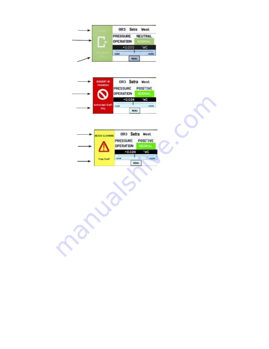
Once the messages of each of the three Condition Banners are defined in the
Menu section, the user can cycle through all three conditions by simply touching
the left one-third of the screen in any region. If passwords are enabled, the user
will be prompted to enter their password before proceeding. Each of the three col-
ored screens can have a unique message defined. See Section: Setup Display, page
11, for instructions on how to setup the Condition Banner.
When the Operating mode of the SRCM is set for PRESSURE = STANDBY, the
top part of all three banners will display STANDBY to indicate that active use of
the SRCM has been suspended and no alarms will occur. See Section, Setup Dis-
play, page 11, for more information on STANDBY mode.
Green Condition Banner
—shows En-
try Permitted graphic, and user defined
text above and below graphic image.
Use the GREEN banner to indicate
room is safe to enter.
Red Condition Banner
—shows
Stop graphic, and user defined text
above and below graphic image.
Use the RED banner to indicate
room is under critical use and entry
Yellow Condition Banner
—shows
Warning graphic, and user defined text
above and below graphic image. Use
the YELLOW banner to indicate room
is under transient use and entry is re-
stricted.
User defined text
ENTRY PERMITTED
graphic (arrow is not intended
to indicate direction of airflow)
User defined text
User defined text
STOP
graphic
User defined text
User defined text
Warning
graphic
User defined text
Condition Banner –
Touch Screen
Operation
-3-
Summary of Contents for SRCM
Page 1: ...Model SRCM Operation...
Page 3: ......


