SerVision UVG400 Installation Manual Download Page 14

SerVision  

UVG400 Installation Guide 


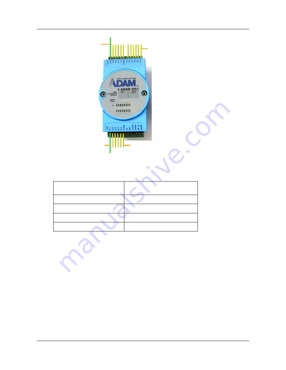
Figure 8: Connecting sensors to the ADAM-4051 module 

3.  Connect the ADAM-4051 module to the ADAM-4520 isolated converter as follows (see figure 10, page 15): 

D GND

Connect sensor ground

wires to this connector

D1 0

 through 

D1 10


Connect positive (+) sensor wires 

to these connectors 

D1 11

 through 

D1 15


Connect positive (+) sensor 
wires to these connectors 

D GND

Connect sensor ground

wires to this connector

Connect this connector on 
the ADAM-4051 

To this connector on the 
ADAM-4520 

(Y) Data+ 

Data+ 

(G) Data- 

Data- 

(R) +Vs 

(R)+Vs 

(B) GND 

(B)GND 


4.  Connect the ADAM-4520 isolated converter to the 

RS232/485

 connector on the rear panel of the UVG400 

unit in one of the following ways: 


If you are not connecting any RS485 PTZ controllers to the unit, using the 9-pin flat ribbon cable, connect 

the RS232 connector of the ADAM-4520 converter directly into the 

RS232/485

 connector.  


If you are also connecting one or more RS485 PTZ controllers to the unit, using the 9-pin flat ribbon 

cable, connect the RS232 connector of the ADAM-4520 converter into the RS232 connector of the 
RS232/485 adapter supplied with the unit. Connect the PTZ controllers to the adaptor as explained under 

Connecting PTZ Controllers

, page 10. Then plug the adaptor into the 

RS232/485

 connector on the unit.  

Connecting Devices to the UVG400 

14 

Summary of Contents for UVG400

Page 1: ...UVG400 Installation Guide September 2013...

Page 2: ...change without notice SerVision Ltd assumes no responsibility for any errors that may appear in this manual Companies names and data used in examples herein are fictitious unless otherwise noted No pa...

Page 3: ...nnecting a Sensor Directly to the Unit 12 Connecting Sensors Using an ADAM Module 12 Connecting Activators 16 Connecting Sensors and Activators Using an IA Relay Board 16 Connecting Microphones 18 Con...

Page 4: ...ocations in which cabled connections are not available garages stables parking lots construction areas etc Once the UVG400 has been installed as explained in this guide it must be configured Configura...

Page 5: ...items Item Description Illustration UVG400 unit Video Gateway Power supply cable Connects the unit to an electrical outlet Ethernet LAN cable Connects the unit to a network RS232 485 serial adapter C...

Page 6: ...ted Please contact your UVG400 supplier or SerVision technical support for a list of supported WiFi cards Up to four dry contact sensors see Connecting Sensors page 11 Note Up to four dry contact sens...

Page 7: ...Connect the cameras and other devices to the UVG400 and to a power supply as required see Connecting Devices to the UVG400 page 10 9 Place the cellular modem in an appropriate location in the vehicle...

Page 8: ...io Out Aout Audio In2 Ain2 Audio In1 Ain1 TV Out Ethernet Cable Video In Vin1 Vin4 Installing the UVG400 System 8 Figure 1 UVG400 connectors and controls RS232 485 USB Ports Mouse Connector Sensors In...

Page 9: ...Vin1 Vin4 Connectors for video cameras see page 10 Ethernet Cable Cable connecting the Video Gateway component of the UVG400 to the unit s router Do not disconnect RS232 485 Serial COM port for PTZ co...

Page 10: ...ures pan tilt zoom and or focus and uses a supported PTZ protocol you can connect the control cable to the unit Both RS232 and RS485 PTZ connection types are supported Consult the camera documentation...

Page 11: ...to the negative grey wire of the adapter see figure 3 Figure 3 RS232 485 adapter To connect multiple RS485 controllers to the adapter insert the positive wires of all of the controllers into one slot...

Page 12: ...display on the monitor For additional information see Connecting a CCTV Monitor page 19 and refer to the Embedded Video Gateway System Guide D To connect a sensor or switch directly to the unit 1 Inst...

Page 13: ...r please refer to the manufacturer s documentation or contact your vendor D To connect sensors using an ADAM module 1 Install the sensors in their desired locations in accordance with the manufacturer...

Page 14: ...onnect the ADAM 4520 isolated converter to the RS232 485 connector on the rear panel of the UVG400 unit in one of the following ways If you are not connecting any RS485 PTZ controllers to the unit usi...

Page 15: ...lows see figure 10 page 15 Connect the positive wire of the power supply cable to the R Vs connector on the module Connect the negative wire of the power supply cable to the B GND connector on the mod...

Page 16: ...te The wires must be connected to two adjacent contacts in the same group e g the two contacts of Out1 but the polarity does not matter Figure 11 Connecting an activator that has its own power supply...

Page 17: ...3126 2 relay board to the UVG400 1 Set the ID of the relay board to 0 For information about how to do this consult the relay board documentation 2 Connect the relay board to the RS232 485 connector o...

Page 18: ...f the Audio In connectors Ain1 and or Ain2 Passive microphones which require external amplification must be connected to Ain1 Active self amplifying microphones must be connected to Ain2 Microphones w...

Page 19: ...ors When choosing a monitor to connect to the unit ensure the monitor supports the video format used by the cameras NTSC or PAL Some SECAM monitors will also work when the PAL video format is used To...

Page 20: ...e display on the monitor The switch must be connected to the Sensor 4 In4 connector For additional information see Connecting Sensors page 11 and refer to the Embedded Video Gateway System Guide Conne...

Page 21: ...hat has a USB adaptor to one of the USB ports on the rear of the unit To ensure good reception use a USB extension cord to connect the modem to the USB port and place the modem in a relatively exposed...

Page 22: ...nt and port forwarding is automatically configured D To connect a device to the UVG400 s local network Connect the network connector of the device to one of the Ethernet In connectors on the rear pane...

Page 23: ...t displays as a solid green or orange all the time the start up process was not successful In this case disconnect the unit from the power supply and then reconnect it WARNING Only the power supply ca...

Page 24: ...UVG400 Installation Guide POB 45205 Jerusalem 91450 Israel Tel 972 2 535 0000 Fax 972 2 586 8683 www servision net info servision net...

Reviews: