Soluciones y Tecnologías de Control Embebido S.A.P.I. de C.V.
www.sepradel.com [email protected] +52 1 833-389-4054
7
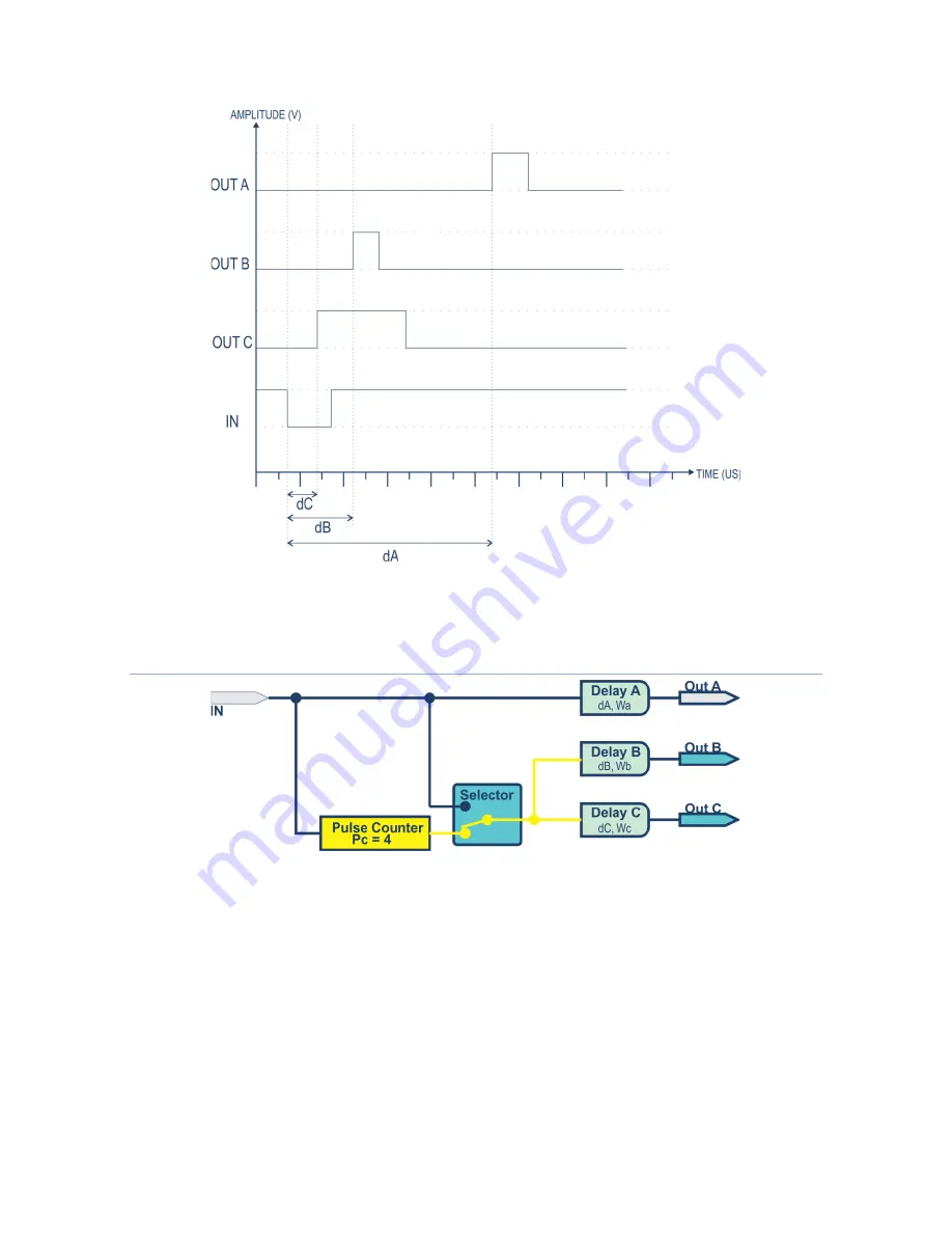
Fig. 6. Behavior of the outputs with respect to a negative logic input pulse, with falling edge detection activated at
IN input
Device behavior activating the pulse counter
Fig. 7. Structure of the Delay Generator when the Pulse Counter is activated, in the example it was configured to
detect 4 rising edges
The following graph shows the behavior of the outputs with respect to successive “IN” input
pulses. Note that the output channel "Out A" emits a delay pulse "dA" and width "Wa" for each
rising edge detected in "IN", while the outputs "Out B" and "Out C" emit their pulses with delays
and widths "dB", "Wb" and "dC", "Wc", respectively when the pulse count configured in the "Pulse
Counter" module is reached, in the case of the example it was configured to count four edges of
rise at the "IN" entrance.


