© Sensor Technology Ltd 2019
RWT3350R (Rev8)
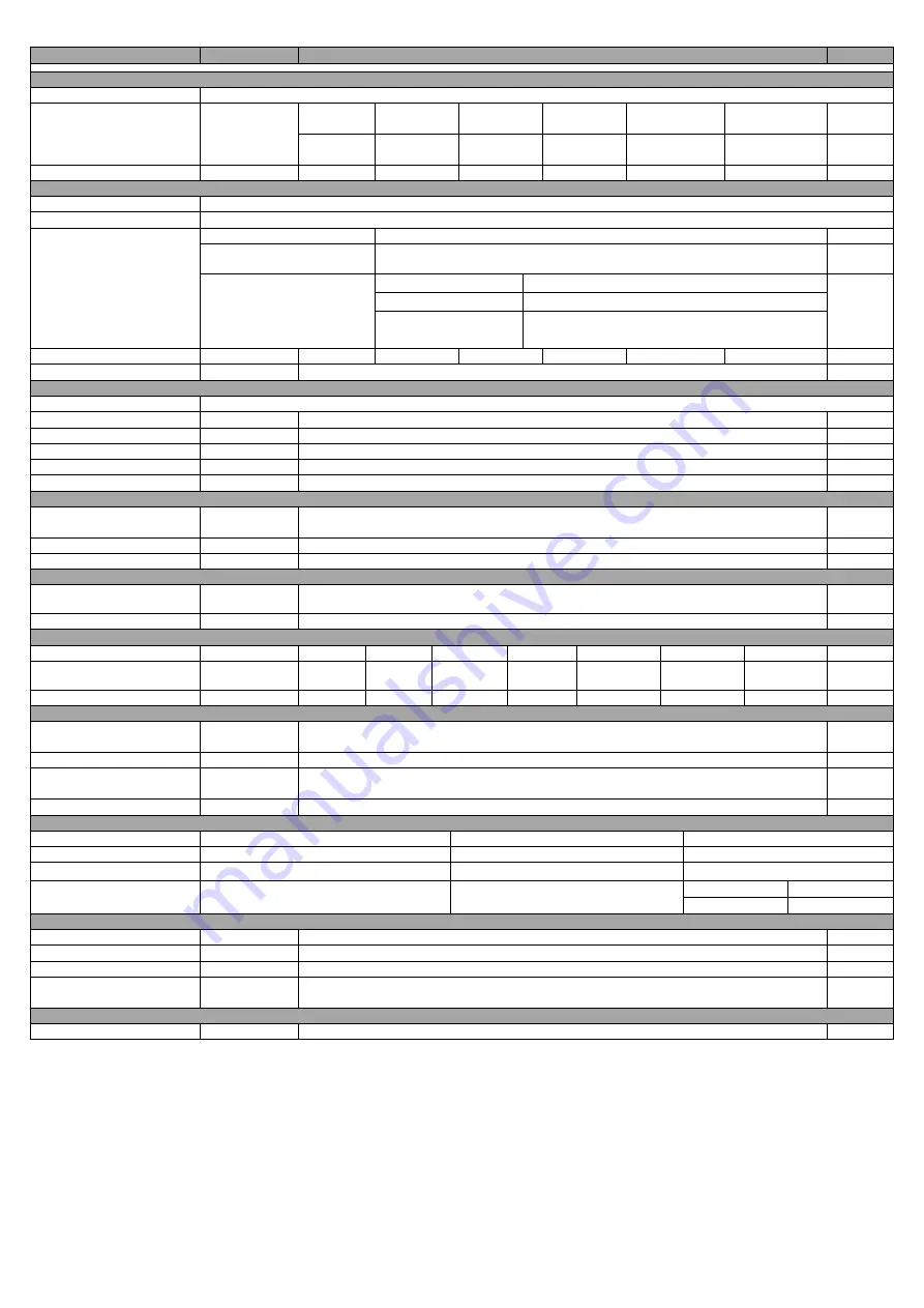
RWT430/440 Series Torque Transducers - Data Specification
Note 1:
Any torque/FSD is possible between ranges – please specify max rated torque.
Note 2:
Max rated torque should not be exceeded.
Note 3:
Please consult factory for applications requiring rotational speeds that exceed maximum figures given. Transducers fitted for IP65 will have
running speeds considerably reduced, increased drag torque and accuracy can be affected.
Note 4:
SM – Static Mode. Dynamic values will depend upon user application and has to be adjusted accordingly.
Note 5:
Digital averaging can be configured by user to optimise accuracy/frequency response for specific user applications. Digital averaging default
setting is N=16. For details see User Manual.
Note 6:
>5Khz Sample Rate. Up to 10Khz sample rate possible, please consult factory. Digital averaging also affects the analog output, max analog output
3dB Bandwidth = 5Khz when digital average is 1.
Note 7:
Output rate figures are calculated from the time taken to capture 10000 torque readings. Testing was conducted with each connection method
configured at its maximum baud rate. The maximum output rate available for CAN and USB is dependant on the transducers setup. USB - USB is a
host based bus architecture, because of this the output rate achievable will be affected by other bus traffic and host activity. USB has two transfer
modes, Single Transfer which requests 1 reading at a time and Bulk Transfer which transfers readings in blocks of 50 Torque/Speed pairs. CAN
Bus - to achieve a Torque reading output rate of 10KHz, the Speed reading output rate must be reduced to 100Hz.
Parameter
Condition
Data
Units
RWT430/440 Torque measurement system
Measurement method
Strain Dependent Surface Acoustic Wave Resonators (interrogated by an incremental electronic scanning method)
Torque range
(See Notes 1 &
2 below)
0 – 1
0 – 1.1
to 0 - 20
0 – 21
to 0 - 100
0 – 101
to 0 - 500
0 - 501
to 0 - 2000
0 – 2001
to 0 - 13000
Nm
[0 - 10]
[0 – 11
to 0 - 200]
[0 – 201
to 0 - 1000]
[0 – 1001
to 0 - 5000]
[0 – 5001
to 0 - 20000]
[0 – 20001
to 0 - 175000]
[lbf
.
in]
Shaft size (diameter)
6
12
20
30
50
75
mm
Rotation speed/angle of rotation measurement system
Measurement method
Opto switch through slotted disc
Direct output signal
Pulse output direct from opto switch (TTL, 5V square wave), output is independent of any analog or digital processing.
Digital Processing
Techniques
Processing modes run
simultaneously and can be
applied to either analog
channel or accessed
individually via a digital
connection.
Processing Method
Update rate for analog and digital outputs
Mode 1 (Slow Method)
Frequency Count
1
Hz
Mode 2 (Fast Method)
Period Count
0 RPM
1
Hz
< 2000 RPM
RPM
> 2000 RPM
RPM x ( 1 / (
(RPM - 1) / 2000
+ 1 ) )
Rotational speed (max)
(See Note 3)
30,000
20,000
15,000
12,000
9,000
6,000
RPM
Accuracy
1rpm up to 30,000rpm
Temperature
Measurement method
IR temperature sensor monitoring actual shaft temperature
Temperature accuracy
1
0
C
Reference temperature, T
RT
20
0
C
Operating range, ΔT
O
-10 to +50
0
C
Storage range, ΔT
S
-20 to +70
0
C
Temperature drift (FS)
Max
0.05
%FS/
0
C
Specifications
Combined non-linearity and
hysteresis
0.25 (
0.5 for 2.5Nm and below)
%FS
Resolution
0.02
%FS
Repeatability
0.1
%FS
RWT430 Series Transducers ONLY
Accuracy
20
0
C, SM
(See
Note 4)
0.25 (
0.5 for 2.5Nm and below)
%FS
3dB Bandwidth
(See Notes 5&6)
312 (default ave. = 16)
Hz
RWT440 Series Transducers ONLY
Digital averaging
(See Note 5)
2
4
8
16
32
64
128
N
Accuracy
20
0
C, SM
(See Note 4)
0.7
0.5
0.4
0.25
0.25
0.25
0.25
%FS
3dB Bandwidth
(See Note 6)
2500
1250
625
312
156
78
39
Hz
Analog output
Output voltages
(Torque/Speed/Power)
Options available:
1 /
5 /
10 / Unipolar (RWT430 Series default setting is
5Vdc)
(RWT440 Series output voltages are user selectable)
Vdc
Load impedance
Maximum 1
KΩ
Output currents
(Torque/Speed/Power)
Options available: 4-20 / 0-20 / 12
8
(RWT440 Series output currents are user selectable)
mA
4-20mA Loop resistance
Should not exceed 400
Ω
Digital output (RWT440 Series Transducers ONLY)
Connections
CAN Bus
RS232
USB
Configuration
CAN 2.0B, 11bit Message Identifiers
Data Bits: 8, Parity: None, Stop Bits: 1
USB 2.0 Full-Speed
Baud Rate(s)
1 Mbps, 500 Kbps, 250 Kbps, 100 Kbps
115200 bps, 38400 bps, 9600 bps
12 Mbps
Output Rate (Note 7)
Up to 10 KHz
Up to 1.1 KHz
Single Transfer
Up to 500 Hz
Bulk Transfer
Up to 10 KHz
Power supply
Nominal voltage, V
S
12 to 32 (max)
V
Current consumption, I
S
230 (max) @ 12 VDC
mA
Power consumption, W
S
3
W
Allowed residual ripple of
supply voltage, V
ripple
500
(above nominal supply voltage)
mVp-p
Electromagnetic compatibility
EMC compatibility
EN 61326:2006
Data parameters measured at +20°C
Sensor Technology Ltd reserves the right to change specification and dimensions without notice.
Summary of Contents for RWT440
Page 23: ......
Page 32: ......
Page 33: ...Transducer Control 5 User Manual Version 5 6 Revision 7 September 2020 ...


