


User Configured Device Display
The user configured device display can be used to show a variety of information at a glance. This includes: IP Address,
Scanner Logic status, Wireless/Wi-Fi status, and the status of selected parameters (i.e. if they are in alarm). If the user
configured device display is disabled, then the QRATE Scanner 3300 touch screen will simply show a summary of Flow
Run 1 and Flow Run 2.
IP Address
The IP address used to connect with a QRATE Scanner 3300 via the web interface is displayed at the top left of the user
configured device display. The IP address is assigned when a user connects the device to the network for the first time. If
no address appears in the user configured device display, check for a problem with the Ethernet connection.
Status Indicators (Glyphs)
When the user configured device display is enabled, a row of pictorial status indicators or “glyphs” appears in the top
right corner of the user configured device display. You can use these glyphs to quickly assess the status of the touch dis
-
play, wireless connectivity, and power connectivity once you become acquainted with the symbols and their meanings
(
and
Table 4.1—User Configured Device Display Status Glyph Definitions
).
Additionally, glyphs indicating the parameter status appear to the left of the parameter reading. You can use these glyphs
to quickly identify the status of a parameter (fail, locked, high- or low-system alarm, etc.) See
tus Glyph Definitions, page 64
for more information about the parameter status glyphs.
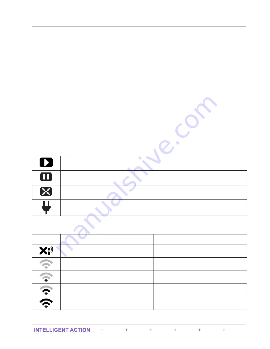
Table 4.1—User Configured Device Display Status Glyph Definitions
Scanner Logic -
RUN.
Scanner Logic -
STOP.
Scanner Logic -
FAIL.
External Power.
An external power source has been detected.
Wireless Communications Status
*By default, this glyph will represent the Wireless Mesh Network. However, if Wi-Fi is present, then Wi-Fi will take over
from the wireless module and this glyph will represent Wi-Fi signal strength instead.
Wireless Mesh Network
Wi-Fi Signal Strength
The wireless transmitter is disabled.
Not applicable.
No mesh nodes are configured.
Wireless Mesh is controlling the signal.
At least one mesh node is configured but none are
operational.
0 < Wi-Fi signal strength < 30
One or more mesh nodes are configured and at
least one is operational.
0 < Wi-Fi signal strength < 75
Multiple mesh nodes are configured and all are
operational.
75 < Wi-Fi signal strength < 100 (Full signal
strength)
63
QRATE Scanner 3300 integrated control flow computer
Section 4


