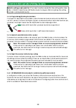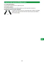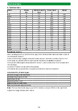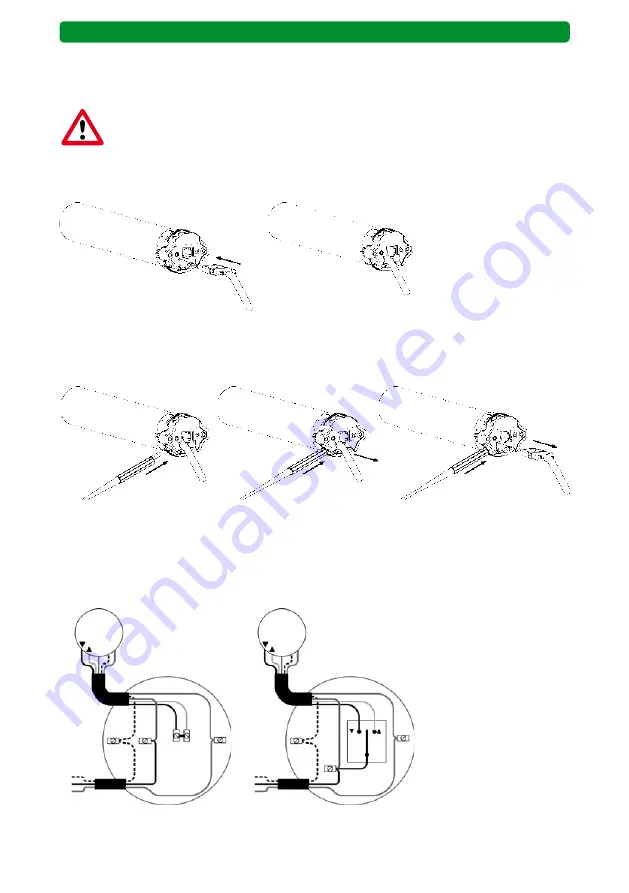
36
3.3. Assembly and disassembly of the pluggable cable
The pluggable cable is not yet implemented for all motor types; some motor types are still
supplied with a fixed cable.
Warning!
Caution! Risk of injury through an electric shock!
When the pluggable cable is unplugged, the line must be de-energised!
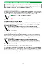
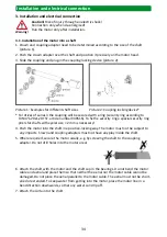
For installing the pluggable cable, de-energise the pluggable cable first. Insert the plug into
the motor head until the lock engages audibly.
For uninstalling the pluggable cable, de-energise the pluggable cable first. Open the plug lock
through the lateral opening at the motor head. This can be done with a screwdriver or a spe-
cial release tool. Press on the locking clip from both sides and carefully pull out the pluggable
cable until the plug comes loose and the pluggable cable can be removed.
3.4. Electric connection
Attention: The SE Plus-com must be connected to a continuous 230 V power supply!
Radio drive without switch,
Radio drive with switch,
Connection cable
Connection cable 5-core
min. 3-core or 5-core
M 1
~
L
L1
N
PE
5
4
3
2
1
PEN
M 1
~
L
L
L1
N
PE
5
4
0
3
2
1
PEN
1 = PE, yellow-green
2 = L1, brown
3 = DOWN, black
4 = UP, grey
5 = N, blue
Connection of a perma-
nently installed switch is
optional. Connection via
N, L1 and PE is sufficient
for radio control only.
Installation and electrical connection

