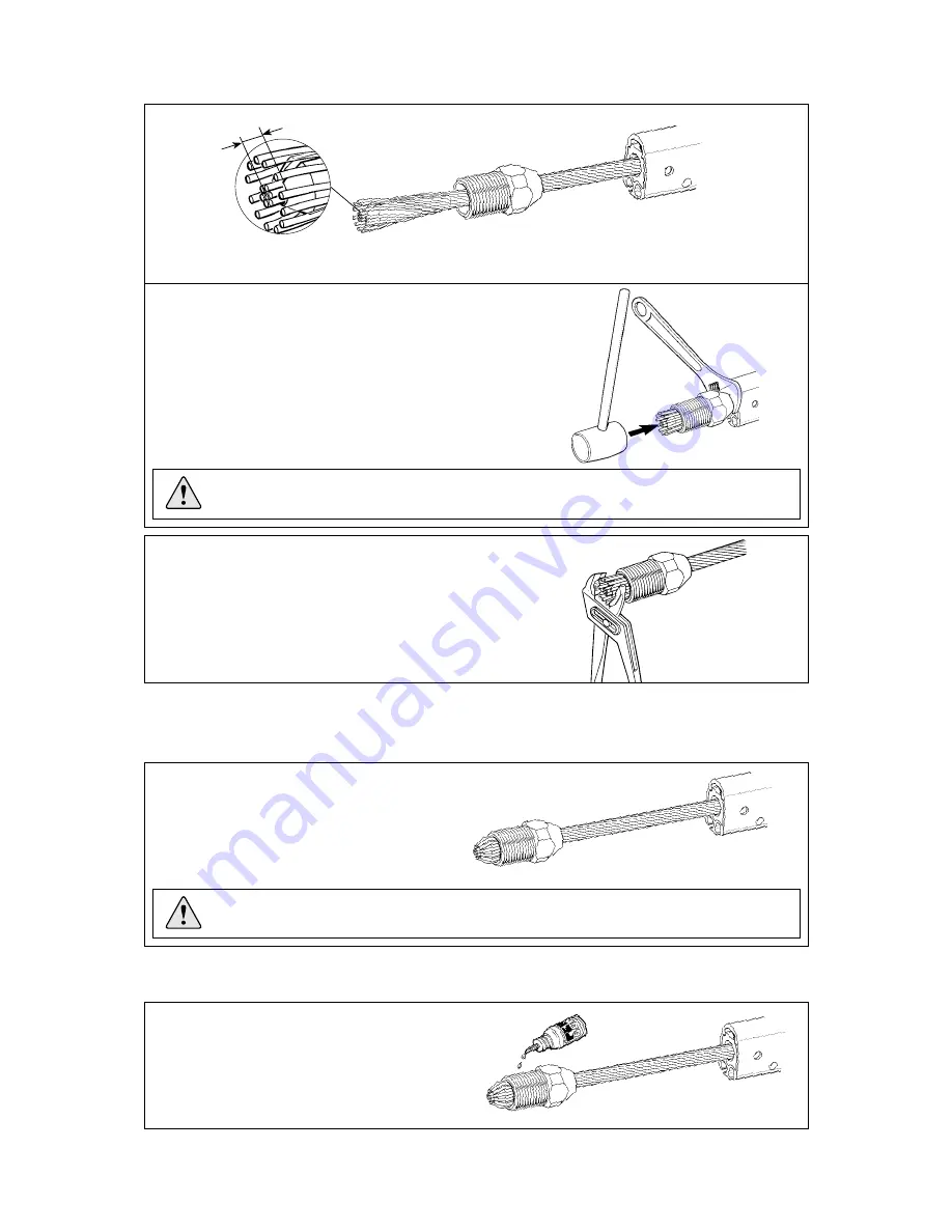
Selden Furlex 400 S Assembly & Operation Manual Download Page 19

19

  9. 


  Slide the wedge over the core (7 strands) of the wire . The core of the wire should protrude approx. 

3 mm (1/8”) from the wedge.

  10. 

  Remove the adhesive tape from the top eye terminal. Space the outer 

strands of the wire evenly around the wedge and bring down the 

  socket so that the strands are held in place. Hold an adjustable 

  spanner between the 1000 mm extrusion and the socket. Tapping the 

core of the wire, locate it firmly in the socket.  

Check that the core of the wire protrudes approx. 3 mm (1/8”) 

  from the wedge. See fig. 4.2.c.

  11.  


Bend the outer strands inwards a little using a pair of pliers,  

or tap the strands with a small hammer. In the latter case,  

rest the socket’s thread on a soft surface (wood or similar) to  

prevent damage.


NOTE! Check that no strands slip into the slot of the wedge.

  13. 


  Unscrew and check that the outer strands are 

evenly distributed around the wedge. If some 

strands are crossed, correct their positions.


NOTE! Check that no strand has slipped into the slot of the wedge!

14.  If assembly is unsuccessful and needs to be repeated, refer to the relevant sections of Chapter 17, 

”Dismantling the Furlex”

.

Fig. 4.2.c

Fig. 4.2.d

Fig. 4.2.n

Fig. 4.2.e

  15.
  Apply another 2 or 3 drops of the locking 

adhesive to the thread and screw the terminal 

together, tightening it firmly. The terminal is 

now permanently locked.

Fig. 4.2.f

3 mm

12.   Insert the former into the threaded hole of the terminal part (or rigging screw). Lubricate the

        socket´s thread with a long bead of locking adhesive. Screw the terminal part onto the socket and

        tighten carefully, forcing the wire further into the terminal.

Summary of Contents for Furlex 400 S

Page 1: ...Manual for assembly and operation Furlex 400 S 500 S 595 116 E 2010 03 08 400 S 500 S...

Page 2: ...o derive the maximum benefit and enjoyment from your Furlex system we recommend that you study this manual carefully The manual is divided into two sections one dealing with ASSEMBLY and one with OPER...

Page 3: ...onto the drum 26 6 3 Routing of the furling line 27 6 4 400 S Fitting the stanchion blocks 28 7 The Sail 7 1 Adapting the sail to the Furlex system 29 7 1 1 Table of sail measurements 30 7 2 Sail shap...

Page 4: ...stem which distributes loads over the entire ball race This permits smoother furling and considerably reduces bearing wear Furlex can be supplied with an optional integral rigging screw The Furlex luf...

Page 5: ...f extrusion 6 Distance tube 7 Joining sleeve 8 Long joining sleeve 9 Sail feeder 10 Sail feeder connector 11 Connecting plate 12 Lower bearing assembly 13 Tack ring 14 Adapter 15 Terminal part or rigg...

Page 6: ...e 400 S 12 Rigging screw adapter Forestay wire with top bearing Wire terminal or Furlex rigging screw Depends on which type ordered Halyard swivel with head shackle Two line drum halves Line guide fit...

Page 7: ...ads 508 128 with insulator sheets incl 6 screws Drill bit 5 3 mm 7 32 Furling line Torx bit set T15 20 25 30 40 45 400 S 500 S 6 stanchion blocks 538 210 01 Locking adhesive Lubricating grease Top gua...

Page 8: ...8 5 16 and 10 mm 3 8 2 3 Tools One 1000 mm 39 3 8 luff extrusion with long joining sleeve bearing plug with bushes 400 S One 1700 mm 67 luff extrusion with distance tube 500 S One 2000 mm 78 3 4 luff...

Page 9: ...e rules and exceptions For H dimensions see Table 3 3 3 The guiding principle is that the forestay connections should allow sufficient articulation in all directions In most cases a toggle should be f...

Page 10: ...ggle or similar toggle with the same function should be fitted between the link and the boat s forestay attachment Fig 3 3 c If a custom made extension link is used it must always have a toggle betwee...

Page 11: ...1 2 Clevis pin D1 19 3 4 22 7 8 Fork width W1 20 5 13 16 20 5 13 16 Eye D2 20 25 32 22 5 7 8 Gauge W2 12 15 32 16 5 8 Eye Fork toggle 3 3 3 Table of measurements for toggles Toggles available from you...

Page 12: ...and the access around the forestay is improved The disadvantage is a more complicated route for the furling line increasing furling resistance The diagrams below illustrate various methods of install...

Page 13: ...o far that the threads are no longer visible on the inside The forestay setting should not be adjusted If there is insufficient adjustment in the backstay and the forestay must be adjusted to allow re...

Page 14: ...of the top extrusion Fixed deduction A B C D WL A B C D 400 S C D Max number of 2400 mm 94 1 2 extrusions which together are shorter than C D ex x 2400 C C Length of top extrusion The top extrusion i...

Page 15: ...15 Fig 3 5 a F L E x i s t i n g f o r e s t a y l e n g t h A E C B D W L T...

Page 16: ...izontal surface Connect the luff extrusions one by one as follows Fit the long joining sleeve at the same time as the long connecting plate into a 2400 mm 94 1 2 luff extrusion and guide the sail feed...

Page 17: ...ining sleeve Connect the remaining extrusions according to Table 2 3 6 1 Fit the halyard swivel over the top end of the extrusion slide it down as far as the sail feeder and secure it in this position...

Page 18: ...le in the terminal end fitting Mark the measurement WL carefully on the wire using a marker pen The WL measurement was calculated in Table 1 Chapter 3 5 1 3 The wire is annealed and tapered making it...

Page 19: ...wood or similar to prevent damage NOTE Check that no strands slip into the slot of the wedge 13 Unscrew and check that the outer strands are evenly distributed around the wedge If some strands are cr...

Page 20: ...m Allen key spanner enclosed in the set Apply locking adhesive on the screw Tighten the screws hard Fit the clevis pin and split pin The legs of the split pin are only opened approx 20 ensuring that t...

Page 21: ...ves and put the line in position as shown in fig 4 3 b 4 3 Fitting the line drum and line guide The line drum consists of two halves These are easier to fit after the Furlex is fitted to the boat 1 Fe...

Page 22: ...rew lightly 8 Adjust the alignment of the line guide towards the first lead block and tighten screw See also Chapter 6 3 Furling line arrangement Fig 4 3 g Fig 4 3 h 3 Fig 4 3 f Push the locking block...

Page 23: ...ear Furlex warrantly 5 1 2 Halyard routing Furlex 500 S No halyard leads are included with the Furlex A halyard sheave box must be used with this model See Section 5 2 and fig 5 2 a May lead to 5 Haly...

Page 24: ...readers Stowing a spinnaker halyard parallel to the Furlex stay is not recommended 5 4 Fitting the halyard lead only 400 S The Furlex kit contains 2 halyard leads If the mast is equipped with two geno...

Page 25: ...with the enclosed 5 3 mm 7 32 drill bit using the fitting as a jig It is easiest to drill the holes before the Furlex stay is fitted 3 Fit the halyard leads over the respective halyard as the halyard...

Page 26: ...otectors 6 2 Winding the line onto the drum Turning the luff extrusion by hand wind approx 40 turns of the furling line onto the line drum If the sail s ultraviolet UV protection is fitted on the star...

Page 27: ...by the cockpit is not included in the Furlex kit This needs to be matched indivi du ally to each boat depending on the attach ment points the line arrangement chosen and possibly also the type of oth...

Page 28: ...6 fixed stanchion blocks for fitting on a 25 mm 63 64 stanchion The fixed blocks can be fitted on a 30 mm 1 3 16 stanchions but the standard screws must be replaced by M6 25 mm screws Assembly The bl...

Page 29: ...splice to prevent unintentional removal loss or exchange All the boat s foresails should be adjusted to the correct luff length See 7 3 below There must be a minimum distance of 80 mm 3 5 32 between...

Page 30: ...3 16 535 21 535 21 620 24 7 16 620 24 7 16 7 1 1 Table of sail measurements Fig 7 1 a WLG Tack deduction E Any additional toggle or link must be added to E DLG 7 2 Sail shape The design of a sail can...

Page 31: ...the length of the rope directly to the head of the sail by a talurit splice This cannot then be removed unintentionally lost or exchanged Smaller foresails such a cruising working jib will have a high...

Page 32: ...in brackets This information must be followed to avoid damage to the system and the risk of personal injury The 5 year guarantee on the Furlex system is only valid if the system is operated correctly...

Page 33: ...and reefing system The angle between the halyard and the forestay must be 5 10 See fig 5 4 b If the angle is less the halyard may wrap around the luff section when the sail is being furled possibly da...

Page 34: ...on which Furlex is to be fitted are always fitted with a sheave box Sheave box kits with assembly instructions are obtainable from all Furlex dealers See Table 5 2 1 and fig 5 2 a for further informa...

Page 35: ...t a figure of eight knot in the ends 6 Fasten the pre feeder to a strong point on the deck or to the tack shackle The line should be approx 500 mm 20 long or 200 mm 8 if tied to the tack shackle Guide...

Page 36: ...are on the drum When furling in strong winds the sail will roll more tightly requiring more turns on the line drum and meaning that more line will be needed Make sure you always have sufficient turns...

Page 37: ...ail tightly and evenly as a sail which is furled too loosely can blow out a little in strong winds If the boat is left unattended the sail may flap until it tears A very loosely furled sail may also c...

Page 38: ...d the foot are furled Since the tack is rein forced by several layers of sail cloth this will increase the sail roll more with each revolution than the rest of the luff thereby impairing the shape of...

Page 39: ...umber of furling revolutions Adjustment of the sheeting position is made considerably easier if a floating sheet point arrangement is used The traveller position is adjusted along the track by means o...

Page 40: ...twin groove racing headfoil The line guide and line drum are dismantled without removing the forestay from the boat and the halyard swivel lowered below the sail feeder When racing with a large crew t...

Page 41: ...osen one of the screws in the adapter holding the luff extrusion Get a strong grip on the luff extrusion before loosening the other screw Then slowly guide the luff extrusion system down until this is...

Page 42: ...hortened See Dismantling Chapter 17 and Assembly of the Furlex system Chapter 4 A Furlex system can be retrofitted with a rigging screw Contact your Furlex dealer Fig 14 1 c Body Forestay dimension 10...

Page 43: ...y other lubricating cycle should be sufficient D F C 1 1 E A B Tools 1 Torx spanner or screwdriver The Torx spanner set supplied with the Furlex system is suitable 1 pair of long nosed pliers For best...

Page 44: ...oat polish or wax This offers good protection and prevents particles of dirt from adhering and then soiling the sail The stainless steel components can be treated with a suitable polish 15 4 Storage T...

Page 45: ...re no free headsail halyards use the main halyard For further information see Seld n Mast AB s Hints and Advice on Working aloft or contact your Furlex dealer 7 Rigging screw Adjust the forestay to th...

Page 46: ...ng the mast with Furlex fitted 1 Lay the mast with the front uppermost 2 Connect the top end of the Furlex system to the forestay attachment 3 Lift the mast with the Furlex system lying on the leading...

Page 47: ...ilfeeder connector s seat 17 3 Lineguide 1 Unwind all the line from the line drum Note the number of turns of line for reassembly Loosen screws and slacken screw off a few turns Lower the line guide f...

Page 48: ...4 Remove the terminal or rigging screw assembly from the socket The thread is held by a locking adhesive If it cannot be turned heat the terminal rigging screw to approx 100 C 212 F and unscrew the t...

Page 49: ...he forestay Check that the shape of the wedge was not damaged on dismantling If so replace it Cut the wire core flush with the outer strands Remove any burrs with a file The decrease in forestay lengt...

Page 50: ...water 3 Refit the support plug into the 1000 mm luff extrusion Then follow Chapter 4 Assembly of the Furlex system 18 Trouble shooting Problem Probable cause Action The sail will not unfurl or will o...

Page 51: ...line Unfurl with slight drag on the furling line in future and avoid having too much line on the drum Loosen the fastening screw below the drum and adjust the fitting Fit the halyard swivel correctly...

Page 52: ...ped around the luff extrusion Check that the line guide eye does not deflect the furling line too much as this can cause extra friction and wear Check that the free turn is functioning i e the tack sw...

Reviews: