16
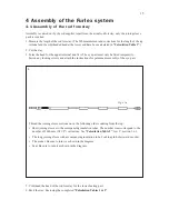
4.2 Assembly of the luff extrusion
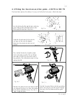
Assembly should be carried out on a horizontal surface. Connect the extrusions after each other as follows:
1. Unscrew the eye part of the upper terminal. Wind tape around the exposed thread of the male part to
protect it.
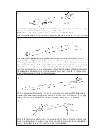
2. Each extrusion must be pushed on over the short joining sleeves from the upper end of the stay in
turn. Push the short joining sleeves up towards the upper end terminal and secure them in position
with tape around the stay.
Push the short lower luff extrusion over all the short joining sleeves and partly over the long, lowest
joining sleeve.
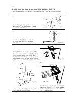
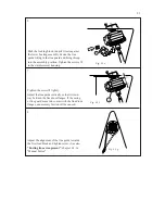
Fit the long connecting plate at the same time as the sail feeder as shown in the diagram. Push the
joining sleeve up so that it is flush with the top edge of the sail feeder.
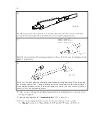
Connect a 2400 mm (94 1/2") extrusion to the lower extrusion. Push the long joining sleeve of the
lower extrusion into the 2400 mm (94 1/2") extrusion until it lies flush with the lower edge of the
lower extrusion.
Fig. 4.2.a
Fig. 4.2.b
Fig. 4.2.c
3.
4.
5.
Summary of Contents for Furlex 200 TD
Page 23: ...23 Notes Comments...

