18
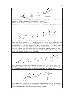
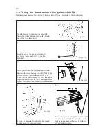
Screw out the socket on the wire terminal part and remove the wedge and former. These three parts
are no longer required. Put 2–3 drops of locking fluid on the thread and screw the terminal together.
Check that the rod head sits correctly in the seat and that the seat is in the socket correctly. Tighten it
securely. This is now permanently locked.
12. Fit the eye part of the upper end terminal permanently with locking ad any stop screw/
locking pin supplied.
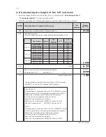
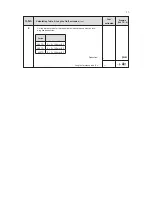
13. Check the stay length FL in
"Calculation Table 1"
(3.5.1) & fig. 3.5.a.
14. We recommend rigging the Furlex system in the boat at this stage of the assembly.
See "
Rigging
" section 16 in "Manual Furlex 200 TD and 300 TD" (part no: 595-231-S)
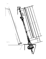
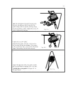
Fig. 4.2.j
12.
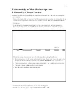
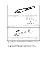
Feed the adapter on to the adapter tube and carefully slide them onto the lower end of the luff
sections. Protect the adapter tube and luff section exterior surfaces from scratches.
10.
Fig. 4.2.h
Fig. 4.2.i
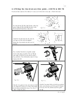
200 TD : 53 mm (2")
300 TD : 66 mm (2 5/8")
400 TD : 79 mm (3 1/8”)
Mark the lower extrusion with a permanent marker as shown. This will assist final alignment with
a adapter tube
11.
Summary of Contents for Furlex 200 TD
Page 23: ...23 Notes Comments...

