34
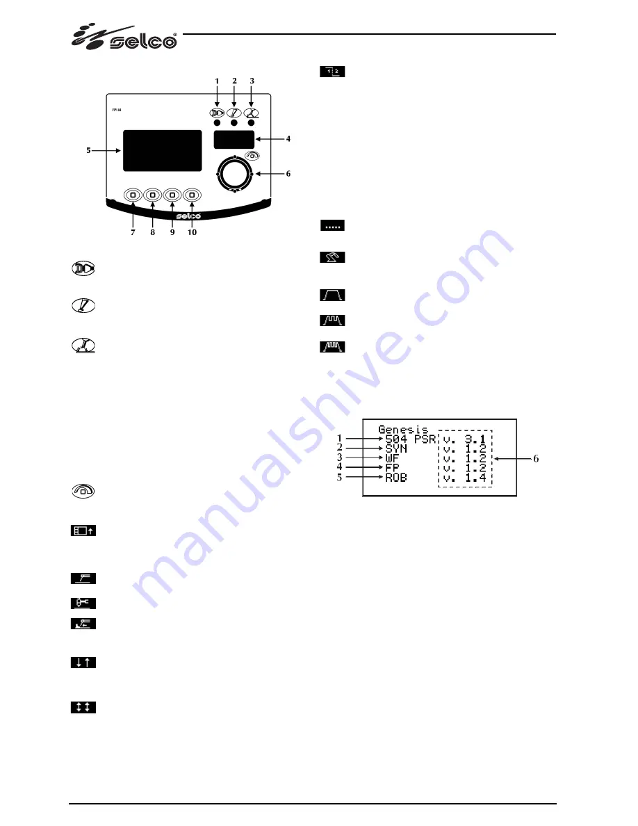
3.3 Front control panel (RC 300)
1 Power
supply
Indicates that the equipment is connected to the mains
and is on.
2 General
alarm
Indicates the possible intervention of protection devices
such as the temperature protection.
3 Power
on
Indicates the presence of voltage on the equipment
outlet connections.
4 7-segment
display
Allows the general welding machine parameters to be
displayed during start-up, settings, current and voltage
readings, while welding, and encoding of the alarms.
5 LCD
display
Allows the general welding machine parameters to be
displayed during start-up, settings, current and voltage
readings, while welding, and encoding of the alarms.
Allows all the operations to be displayed instantaneously.
6
Main adjustment handle
Allows entry to set up, the selection and the setting of
the welding parameters.
7
Quick choice menu
Allows access to a limited group of parameters and
allows their regulation.
8 Welding
process
Allows the selection of the welding procedure.
Electrode welding (MMA)
TIG welding
ARC AIR
9 Welding
methods
In
2 Step,
pressing the button causes the gas to flow and
strikes the arc; when the button is released the current
returns to zero in the slope descent time; once the arc
is extinguished, the gas flows for the post-gas time.
In
4 Step
the first pressure on the button causes the gas
to flow, performing a manual pre-gas; when it is
released the arc is struck.
The following pressure and the final release of the but-
ton cause the current slope descent and the post-gas
time to start.
In
BILEVEL
the welder can weld with 2 different cur-
rents previously set with “set up”.
The first pressure on the button leads to the pre-gas
time, the striking of the arc and welding with the initial
current.
The first release leads to the current slope-up “I1”. If the
welder presses and releases the button quickly, there
is a change to “I2”; pressing and releasing the button
quickly returns to “I1” and so on.
Pressing it for a longer time starts the current slope-
down which leads to the final current.
Releasing the button extinguishes the arc while the gas
continues to flow for the post-gas time.
Spot
welding
Allows you to enable the “spot welding” process and to
establish the welding time.
Automation and robotics
Allows setting of the welding parameters by external
systems such as the robots.
10 Current
pulsation
CONSTANT current
PULSED current
MEDIUM FREQUENCY current
3.4 Starting Screen
When switched on, the generator performs a succession of
checks in order to guarantee the correct operation of the system
and of all the devices connected to it.
1 Logic/system type board
2 Synergic board
3 Motor board (WF)
4 Control board (RC 300)
5 Robot interface board (RI)
6 Software version
The lack of the software version shown alongside a device (---)
indicates lack of communication with it, and correct operation
is therefore not guaranteed (consult the “Diagnostics and solu-
tions” section).
At this stage the gas test is also carried out to check the proper
connection to the gas supply system (system for automation and
robotics).
Any lack of gas flow sets off a dedicated audible and visual alarm
signal (consult the “Alarms” section).
Summary of Contents for Genesis 284 PSR
Page 50: ...50...
Page 76: ...76...
Page 102: ...102...
Page 198: ...198...
Page 270: ...270...
Page 274: ...274 1 3 1 4 11 35 1 5...
Page 275: ...275 1 6 8 1 7 EN IEC 60974 10 B A A EN60974 10 A pace maker Point of Commom Coupling PCC...
Page 276: ...1 8 IP S IP23S 12 5 mm 60 2 2 1 2 2 10 2 3 400V 15 15 2 1 5 276...
Page 277: ...277 2 4 MMA 1 2 3 4 TIG 1 2 TIG 3 4 1 2 3 4...
Page 284: ...284 3 9 1 50 1 3 3a 3b 3c 3d 3e 2 encoder 1 1 4 encoder encoder 1 4 4 3 encoder 2...
Page 290: ...290 4 5 MT300 5 6...
Page 291: ...291 Reset encoder...
Page 292: ...292...
Page 296: ...296...
Page 300: ...GENESIS 504 PSR 300...
Page 304: ...304...


