


Installation Instructions TM50/TM80 - MO911/1V0
Page 3
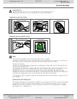
Adjusting the Door Type
Sectionaldoor
Tilting Door
Canopy Type Doors
Canopy Type Doors
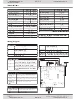
Free Programming
After changing the DIP-switch settings the operator MUST run through a learning cycle: keep the
LEARN button pressed for 3 seconds, release it and press it again shortly�
For free programming, pls�
refer to page 13�
Increased Force shortly before reaching Closed Position
Standard
Increased Force
Changing the DIP-switch settings must be confirmed by shortly
pressing the LEARN button�
Pre-Warning Light
(always active when using automatic closing, pls� refer to page 14 )
Off
ON
Changing the DIP-switch settings must be confirmed by shortly
pressing the LEARN button�
Automatic Closing
None
after 30 sec�
after 90 sec�
after 120 sec�
Changing the DIP-switch settings must be confirmed by shortly pressing the LEARN button�
Connectors
Push Button (potential free)
A + B
Photo Cell and Hatch Door, 8�2 kOhm,
Remove resistor and connect it to the photo cell
by putting it in line with one impulse wire
C + D
24V AC Output, max� 200mAmp�
24 V
Programming
Running Length and Forces
Keep the LEARN button pressed for 3 seconds, release it (the operators‘ light is now
blinking) and press it again shortly
Remote Components (Transmitters, Digi
Pad, Remote Wall Push Button)
Keep the LEARN button pressed for 3 seconds, release it (the operators‘ light is now
blinking) and press the desired hand transmitter button
Changing the Duration of the
Internal Lighting
Keep the LEARN button pressed for 6 seconds, release it once the green LED starts
glowing� Press LEARN button once again shortly -> the green LED starts blinking� Each
blink stands for 10 seconds of light duration� Once the desired duration is reached,
press the LEARN button again shortly (e�g� after 6 blinks for a duration of 60 seconds)�
LED-Indicators
Vp (yellow)
On when 230V supply is o�k�
TEST/FUNK (green)
On whilst an impuls is received from remote devices or a connected push-button (A+B)
8k2/Diag (red)
On when an error from a connected safety device is received (connectors C+D) or
blinks in intervalls to indicate error messages (refer to page 19)
Quick Reference for experienced Installers
www.thegaragedoorcentre.co.uk
0800 525 442
www.thegaragedoorcentre.co.uk
www.thegaragedoorcentre.co.uk
0800 525 442
www.thegaragedoorcentre.co.uk


