Installation Instructions TM50/TM80 - MO911/1V0
Page 18
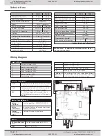
Technical Information
Technical Data
Wiring Diagram
TM 50
TM 80
Nominal Pulling Force
50 kg
80 kg
Peak Pulling Force
60 kg
90 kg
Force-Setting for Operation
automatic
Motor
24V DC, low-noise
Max� Running Speed
18 cm/sec�
14 cm/sec�
Speed in Soft Mode
8 cm/sec�
8 cm/sec�
Time for 2,10m opening
11,5 sec�
16 sec�
Lighting
230V AC, max� 40W
Lighting Durance (adjustable)
10 sec� to 10 minutes
Duty Cycle
50%
Stand By Power Consumption
2�0 watts
Power Supply
190-250V AC
Transformer
230V AC, 24V AC
Pre-Warning Light
adjustable
Automatic closing
adjustable
TM 50
TM 80
Net Running Length
2,500 mm
Max� Running Length extended
4,000 mm
Overall Length
3,150 mm
Height Motor Head
80 mm
Length Motor Head
360 mm
Width Motor Head
180 mm
Minimum Space above the door
35 mm
Weight including packaging
18 kg
Noise Emissions
≤ 60 dB(A)
Programmable Remotes
10 max�
Max� number of cars/garage
1
3
Subject to technical alterations!
Maintenance: The operator is maintenance free! Do not
grease or oil the chain!
Internal Wiring
1
Blue, mains supply, 230V
2
Brown, mains supply, 230V
3
Black, transformer, 230V
4
Black, transformer, 230V
5
Brown, Lighting, 230V
6
Blue, Lighting, 230V
External connections
A + B
Floating connector for push-button, key-switch
and the impulse cables of an external receiver
C + D
Floating connector with a 8,2kOhm resistor for
impulse cables from a photo-cell receiver
24V
24V AC for a photo cell transmitter when a
self test before every movement of the door is
required
Others
HF-Modul/Receiver
Card
Plug for receiver module, 433 MHz
FUSE
Fuse T1,6A 250V
Devices for adjustments
Button
„Test/Run“
Runs the operator - OPEN-STOP-CLOSE
Button
„Lern/Learn“
For automatic force setting and registration
of hand transmitters
Jumper
“FORCE/PRES-
SURE”
Setting of lower or higher force
7
White, transformer, 24V
8
White, transformer, 24V
9 MOTOR
Connector for the plug from the motor
PE
Earthing from P�C�B� to base plate
Earthing of
the mains
supply
The earthing of the mains supply (green/yellow)
is connected to the base plate with a screw (the
screw is marked with a earthing symbol)
www.thegaragedoorcentre.co.uk
0800 525 442
www.thegaragedoorcentre.co.uk
www.thegaragedoorcentre.co.uk
0800 525 442
www.thegaragedoorcentre.co.uk


