


LERN/
LEARN
B A
DIP
HF-Modul
D C 24V
TEST/
RUN
Installation Instructions TM50/TM80 - MO911/1V0
Page 11
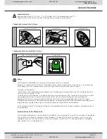
Printed Circuit Board: Adjustments and Connectors
Push Button
A + B
Connector for a wired wall push button
Standard function
Pressing the push button will give a command to the operator� Whether this is an opening,
closing or stop command depends on the entire status of the operator�
Function when using
the automatic closing
feature
Pressing the push button:
will give an opening command when the door is closed
will be ineffective when the operator is running into opening direction
will extend the time the door is kept open when the door is in open position already
will give an opening command when the operator is running into closing direction
To avoid the automatic closing occassionally, a standard wall switch may be connected� Whilst
it is switched on, the push button connector will be blocked and the operator cannot close the
door unless the wall switch is set to off position� It may be connected parallel together with a
wall push button�
Photo Cell / Hatch Door Contact
C + D
Connector for the impulse wires of a photo cell or a hatch door contact� The 8�2kOhm resistor
is used to survey the wire� It must be removed from C+D and must be connected to the safety
device as shown below�
If both, a photo cell and a hatch door contact, must be used, then both items must be connected
in one line�
Photo Cell:
D
C
24V
24V
24 V
24 V
N.C.
8,2 k
W
Hatch Door Contact:
C
D
8,2 k
W
Standard function
Openings: If the device detects an obstacle within approx� 2 seconds after running from closed
position, then the operator will stop (e�g� hatch door is open)� After these 2 seconds the connec-
tor is not being checked anymore for the rest of the opening run�
Closings: The connector will be checked during the whole closing proceedure� Once an obstacle
is detected, the operator will reverse to fully open�
Function when using
the automatic closing
feature
Openings: pls� refer above to „Standard function“
Closings: The connector will be checked during the whole closing proceedure� Once an obstacle
is detected, the operator will reverse to fully open� The adjusted time for automatic closing will
start running� If the obstacle will be removed after the automatic closing time has elapsed, then
the closing procedure will start immediately�
24V AC Output (200mAmp max.)
24V
24V a/c (max� 200mAmp) power supply for external components (for example photo cells or
remote receivers)
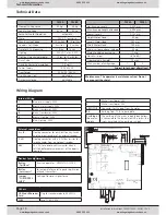
Connectors
www.thegaragedoorcentre.co.uk
0800 525 442
www.thegaragedoorcentre.co.uk
www.thegaragedoorcentre.co.uk
0800 525 442
www.thegaragedoorcentre.co.uk


