


9 -
13
FRONT & REAR SUSPENSION
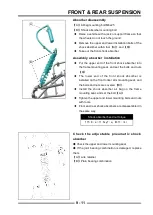
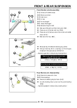
Front Rocker arm disassembly
【
A
】
front brake calipers
【
B
】
Front knuckle assembly
【
C
】
Brake hose fi xing bolt
【
D
】
Steering pull rod nut
【
E
】
Ball pin connecting rod bolt
【
F
】
Rocker arm mounting bolt
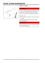
◆
Remove the brake caliper
【
A
】
, remove the pipe
fi xing bolt
【
C
】
◆
Remove steering knuckle component
【
B
】
◆
Remove the brake hose fi xing bolt
【
A
】
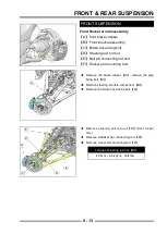
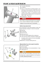
FRONT SUSPENSION
A
B
C
C
A
B
D
E
F
◆
Remove steering pull rod nut
【
D
】
(front rocker
arm)
◆
Remove stabilizer bar connecting rod
【
E
】
◆
Remove rocker arm mounting bolt
【
F
】
Torque of steering rod nut
【
D
】
45 N·m
(
4.6 kgf·m
,
33ft·lbs
)
Summary of Contents for S301000-20100A
Page 1: ...SERVICE MANUAL SSV 4 3 4 130 6 54...
Page 50: ...ENGINE LUBRICATION SYSTEM 3 1 2 Exploded view...
Page 63: ...EFI SYSTEM 3 2 2 Exploded view Exploded view...
Page 67: ...STARTING SYSTEM 3 3 2 Exploded view...
Page 75: ...CRANKCASE CRANKSHAFT BALANCE SHAFT 3 4 2 Explosive view...
Page 76: ...CRANKCASE CRANKSHAFT BALANCE SHAFT 3 4 3 Explosive view of Up and down the case sub assembly...
Page 100: ...CYLINDER HEAD CYLINDER PISTON CYLINDER HEAD CYLINDER PISTON 3 5 3 Exploded view...
Page 141: ...CVT SYSTEM 3 6 2 Exploded view...
Page 151: ...WATER PUMP ASSEMBLY 3 7 2 Exploded view...
Page 197: ...6 6 COOLING SYSTEM SPECIAL TOOLS AND SEALANTS Silicone Sealant Special tools and sealants...
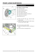
Page 227: ...9 2 FRONT REAR SUSPENSION EXPLODED VIEW OF FRONT SUSPENSION...
Page 229: ...9 4 FRONT REAR SUSPENSION EXPLODED VIEW OF REAR SUSPENSION...
Page 247: ...10 5 WHEELS AND TIRES SPECIAL TOOLS Jack...
Page 261: ...11 4 BRAKE SYSTEM SPECIAL TOOLS Inside Circlip Pliers...
Page 314: ...14 4 ELECTRICAL SYSTEM EXPLODED VIEW...
Page 407: ...14 97 ELECTRICAL SYSTEM ELECTRIC SCHEMATIC DIAGRAM...


