


Commissioning
ASD 531, Technical description, T 140 416 en
77 / 105
7.3.3
Setting the alarm threshold with “ASD Pipeflow” calculation
The following work flow describes the procedure when ASD 531 has to be set to an “ASD Pipeflow” calculated value.
Example
: The ASD 531 is to respond in compliance with EN 54-20, class B. “ASD PipeFlow” calculated a value of 0.346%/m.
Measure
Indicator
Procedure / remarks
(1)
Read the next more sensitive value
from the table in Sec. 4.3.1.1.
--
•
0.337%/m (sensitivity 10 (A) in sensitivity range 2)
(2)
Turn rotary switch “
Class
” to position
“
2
”
--
•
Sensitivity range
2
is set
(3)
Turn rotary switch “
Holes
” to position
“
A
”
--
•
Sensitivity
10
is set
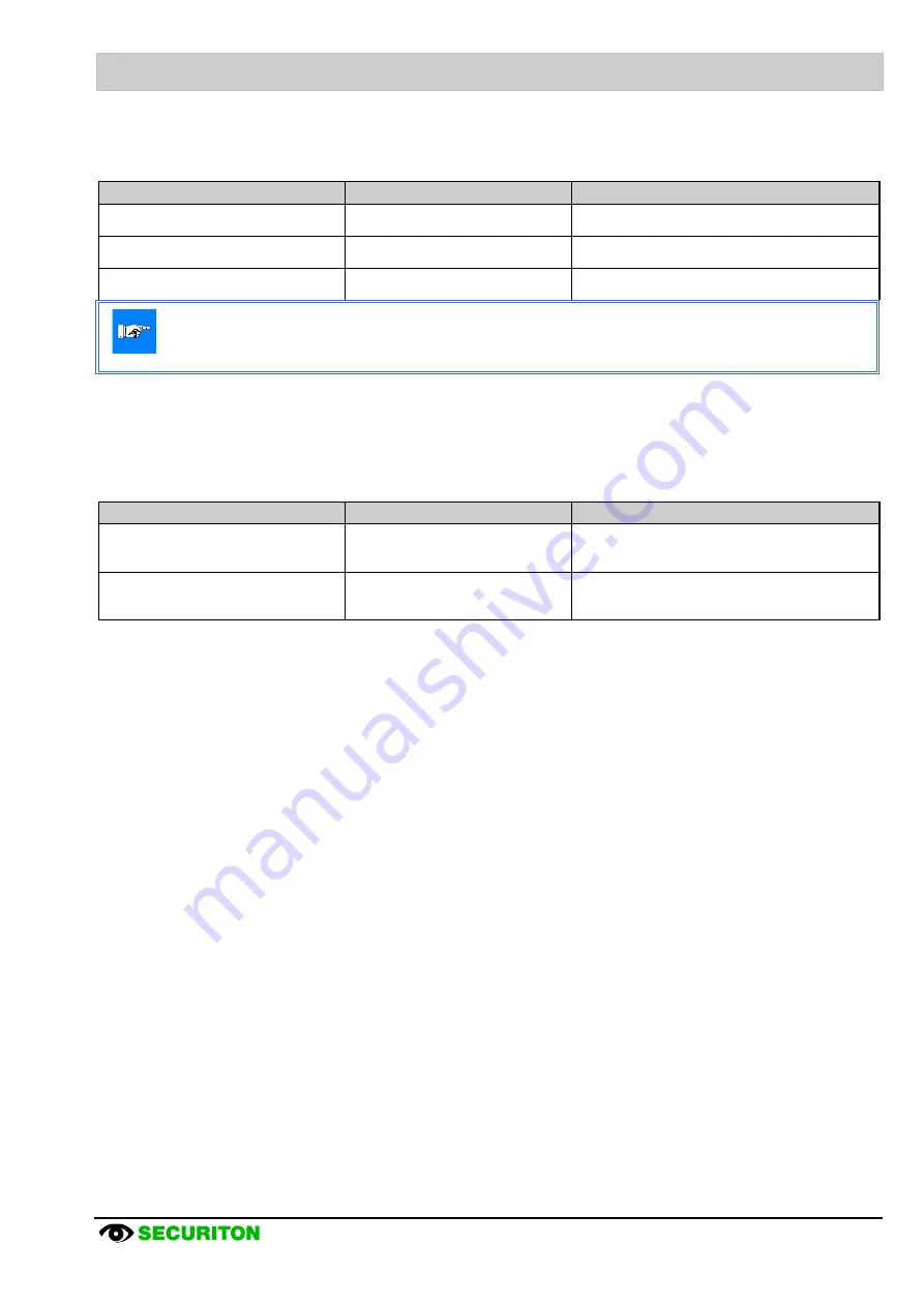
Notice
If there is a false or invalid entry (e.g. EN-Class A with 9 holes), LEDs “
Class
” and “
Holes
”, begin to flash after
a delay time. After a second delay time the ASD triggers a fault.
7.3.4
Setting the air flow tolerance and delay time
The following work flow describes the procedure for setting air flow tolerance and delay time of the ASD 531.
Example
: ASD 531 is to trigger a fault if there is a deviation of ±30% after 20 min. Perform the settings as described in
Sec. 7.2.1.2.
Measure
Indicator
Procedure / remarks
(1)
Set Dip switch “
Airflow
”:
Switch 1 on “
OFF
”
Switch 2 on “
ON
”
--
•
Air flow tolerance set to
±30%
(2)
Set Dip switch “
Airflow
”:
Switch 3 on “
ON
”
Switch 4 on “
OFF
”
--
•
Delay time set to
20 min