background image

6

Installation

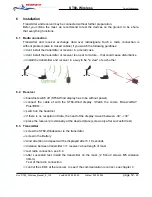
Transmitter and receiver may be connected without further preparation.
Befor you climbe the mast, we recommend to test the devices on the ground, to be shure,
that everything functions.

6.1 Radio connection

Transmitter and receiver exchange data over radiosignals. Such a radio connection is
without problem (also in closed cabine) if you watch the following guidlines:

dont install the transmitter or receiver in a metall case

dont install the transmitter or receiver too near to motors.... that could cause disturbance

install the transmitter and receiver in a way to be "in view" of each other

6.2 Receiver

boardnet switch off (ST60-Wind display has to be without power)

connect the cable of with the ST60-Wind display. !Watch the colors. Minus=GRAY
Plus=RED.....
switch on the boardnet

if there is no reception of data, the hand of the display 'waves' between -30°...+30°

place the receiver provisionally at the desired place (screw only after succesfull test)

6.3 Transmitter

screw the ST60-Windsensor to the transmitter

screw in the Battery

wind direction and speed will be displayed after 5..10 seconds

distance between transmitter <=> receiver: about length of mast

test radio connection. see 6.4

after succesfull test, install the transmitter on the mast. (2 'Imbus' screws M5, distance
30mm)
Test of the radio connection
control the LED's at the receiver, to see if the communication is correct. see chapter 4

ST60- Wireless

Owner's Handbook

Doc:

ST60_Wireless_Manual_E_V10

LastEdit:

03.02.2005

Printed:

03.02.2005

page 12

- 20

Summary of Contents for ST60 Wireless

Page 1: ...ST60 Wireless Owner s Handbook Doc ST60_Wireless_Manual_E_V10 LastEdit 03 02 2005 Printed 03 02 2005 page 1 20 ST60 Wireless cut the cable...

Page 2: ...ation 11 5 1 2 Transmitter turn off battery screw out 11 5 1 1 Battery change 11 5 1 Maintenance 11 5 Maintenance 10 4 5 Configuration switches in the receiver 10 4 4 Learn Mode 9 4 3 Button SW1 and c...

Page 3: ...fter mounting of the battery the transmitter starts periodically measuring the sensor signals and sends this data by radio transmission to the receiver Receiver The receiver converts this data to the...

Page 4: ...ergy consuming measuring It changes automatically in a standby mode with almost no use of current 1 1 2Operation mode As soon as the receiver is switched on the transmitter notices the change and star...

Page 5: ...re marine environment Their design and manufacture conforms to the appropriate Electromagnetic Compati bility EMC standards but correct installation is required to ensure that performance is not compr...

Page 6: ...years recevier OFF bordnet switched off Battery life sailing 2 3 years recevier ON bordnet switched on Storage of battery 5 10 years 1 loss per year Measuring cycles Wind direction every 0 5 10 sec de...

Page 7: ...ceiver or communication error short flash receiption of any data or HF inputs This LED shows reliably if the air is clean from other HF desturbing signals At intensiv flickering of this LED the source...

Page 8: ...ion of valid sensor data wind direction and speed note the transmitter will send data in uneven interval This means that not regular blinking of LED is normal permanent ON no communication for more th...

Page 9: ...learn mode for 60 seconds If during this time a battery is screwed into the transmitter this transmitter and the receiver being in the learn mode start synchronization After successful learning the L...

Page 10: ...ain in to unscrew of approx 10mm is enough If the transmitters makes not a measurement it needs very little current so that short removing of the battery is not enough in order to switch the transmitt...

Page 11: ...ttery Thats all It is sufficient to tighten the battery manually By using 8mm Imbus key please dont squeeze the O Ring too much Note Please pay attention to keep the contact surface of the battery alw...

Page 12: ...has to be without power connect the cable of with the ST60 Wind display Watch the colors Minus GRAY Plus RED switch on the boardnet if there is no reception of data the hand of the display waves betw...

Page 13: ...al installation manual from Raytheon 7 3 ST60 transmitter and or receiver exchange In the case of exchange ST60 Wirless components transmitter receiver or both a new calbibration can be omitted the de...

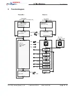
Page 14: ...FACK Timeout timeout OK CS_Idle CS_Test CS_Learn SW1 1 sensor SW1 Test SW1 T Display Timeout FREQ FACK Wind Config Wind Wind LearnREQ Learn Learn measure Sinus Cosinus UBat URef RPM Initialisations S...

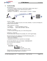
Page 15: ...a device change have you run the learning mode windsensor transmitter The transmitter does not dispose of any display for a most rugged design But the fellowing errors are displayed on the ST60 Wind d...

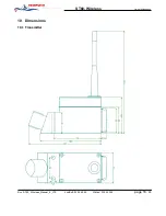
Page 16: ...10 Dimensions 10 1 Transmitter ST60 Wireless Owner s Handbook Doc ST60_Wireless_Manual_E_V10 LastEdit 03 02 2005 Printed 03 02 2005 page 16 20...

Page 17: ...10 2 Receiver ST60 Wireless Owner s Handbook Doc ST60_Wireless_Manual_E_V10 LastEdit 03 02 2005 Printed 03 02 2005 page 17 20...

Page 18: ...11 Declaration of conformity ST60 Wireless Owner s Handbook Doc ST60_Wireless_Manual_E_V10 LastEdit 03 02 2005 Printed 03 02 2005 page 18 20...

Page 19: ...ST60 Wireless Owner s Handbook Doc ST60_Wireless_Manual_E_V10 LastEdit 03 02 2005 Printed 03 02 2005 page 19 20...

Page 20: ...ST60 Wireless Owner s Handbook Doc ST60_Wireless_Manual_E_V10 LastEdit 03 02 2005 Printed 03 02 2005 page 20 20...

Reviews: