


7
Rev. 3.0 13/06/16
LRX 2247 Electronic Control Unit
Electronic control unit, for simultaneous automation of 2 motors
for rolling window shutters and sun blinds installed both on the
same transmission roller and individually. The control unit can
be activated using push button panel and radio control, for indi-
vidual and centralised control, it includes inputs for a wired
Wind, Sun or Rain Sensor. It is also capable of communicating
with the Wind, Sun and Rain Sensors.
- Mod.
LG 2247
: Without Radio Receiver
- Mod.
LRS 2247
:
433,92 MHz
- Mod.
LRS2247 SET
:
“Narrow Band” 433.92
MHz
- Mod.
LRH 2247
:
“Narrow Band” 868.3
MHz
T
ECHNICAL
D
ATA
- Power supply:
230V~ 50/60Hz 1250W max.
- Motor output:
2 x 230V~ 600W Max.
- Working temperature:
-10
÷
55°C
- Radio receiver:
see model
- Compatible radio-controls:
12-18 Bit - Rolling Code
- Amount of Radio-controls that can be memorised: 7 Max.
- Amount of Wireless Sensors that can be memorised: 1 Max.
- Packaging dimensions: 110 x 121 x 47 mm.
- Container: ABS UL94V-0 (IP54)
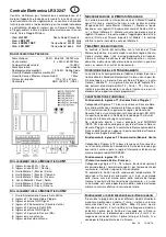
C
ONNECTIONS OF THE
CN1
T
ERMINAL BOARD
9: 230V~ Line input (Phase).
10:
230V~ Line input (Neutral).
11:
Ascent Motor 1 ( Master ) Output.
12:
Common Motor 1 ( Master ) Output.
13:
Descent Motor 1 ( Master ) Output.
14:
Ascent Motor 2 ( Slave ) Output.
15:
Common Motor 2 ( Slave ) Output.
16:
Descent Motor 2 ( Slave ) Output.
C
ONNECTIONS OF THE
CN2
T
ERMINAL BOARD
10: Sun Sensor power supply output 24Vac.
11: Sun or Rain T1 Sensor Input.
12: Common input GND Signal.
13: T2 Anemometer input (Rain Sensor).
14: Ascent button T3 input (NA).
15: Common input GND Signal.
16: Descent button T4 input (NA).
17: Aerial earth input.
18: Aerial hot pole input.
S
YNCHRONISATION OF
2
S
TANDARD
M
OTORS
The control unit allows synchronisation of 2 Standard Motors
that are the same and installed on the same transmission roller.
Motor 1 is defined as Master (Motor that the Mechanical Ascent
and Descent End runs must be adjusted to ) and Motor 2 is de-
fined as Slave (Motor on which the end runs do not have to be
adjusted). This way once the Ascent or Descent end run set on
Motor 1 is reached, the control unit also immediately stops Mo-
tor 2.
A
UTOMATIC
M
OTOR
T
IMER
The control unit is supplied from the manufacturer with the Au-
tomatic Motor Timer function; this way the control unit cuts
power to the motors 1 sec. after the internal motor end run has
been reached or when the motors stop due to overheating.
Moreover, the power to the motors is cut in any case if it ex-
ceeds 4 minutes of operation.
I
NITIAL
F
UNCTIONING
C
ONDITION
Factory settings for the control unit are to control 2 Standard
Motors Synchronised with each other and with the possibility of
connecting a wired Sun or Rain Sensor input T1 (if selected), a
wired Rain Sensor input T2 and two distinct control buttons T3 (
Ascent ), T4 ( Descent ). It must also be possible to command
the control unit using one or more radio controls if properly
trained.
OPERATING FEATURES:
Operation of the T1 input (Sun or Rain Sensor):
By connected a Sun Sensor to the low-voltage T1 input, the
electrical control unit will control blind Descent after 10 minutes
where luminosity exceeds the threshold selected in the Sun
Sensor, displayed when the SUN LED turns on. Subsequently,
it will control Ascent of the blind after 10 minutes of luminosity
under the selected threshold.
By selecting Led SUN/RAIN INPUT ON in the main menu, it is
possible to connect a Rain Sensor instead of a Sun Sensor.
The electronic control unit controls the descent of the blind as
soon as the sensitive part of the Rain Sensor is wet from rain.
T2 Anemometer input operation (Wind Sensor):
By connecting a Wind Sensor to the low-voltage T2 input, the
electrical control unit will control the ascent of the blind every
time wind exceeds the intervention threshold selected in the
Led WIND SPEED main menu.
T3 – T4 input operation
(Ascent – Descent control buttons):
The following type of operation is obtained by connecting the
local command buttons (normally open) for movement activa-
tion to the low voltage inputs T3 – T4:
T3 controls upward movement until the motor running time has
elapsed and T4 controls downward movement. If a command is
sent in the same direction before the motor running time has
elapsed, the control unit will stop movement; if a command is
sent in the opposite direction before the motor running time has
elapsed, the control unit will invert the direction of the motor.
F
UNCTIONING WITH DIFFERENT
R
ADIO
-
CONTROLS MODELS
IT is possible to program different radio control models: by
memorising a code (1 key) a Step-by-Step cyclical functioning
is obtained; (Ascent -Stop-Descent) by memorising two differ-
ent codes (2 keys) distinct controls are obtained. The first for
Ascent and the second for Descent, by memorising a BeFree
series radio control (3 keys) distinct controls are obtained, the
first for Ascending, the second for Stopping and the third for
Descending.
GB


