background image

Jumper 25               


Instruction Man u al

13


10) After  the  epoxy  has  fully  cured, 

re move the masking tape or T-pins used to 

hold the sta bi liz er in place.  Carefully inspect 

the  glue  joints.    Use  more  ep oxy  to  fi ll  in 

any gaps that may exist that were not fi lled 

previously and clean up the excess using a 

pa per towel and rubbing alcohol.

VERTICAL STABILIZER

INSTALLATION

PARTS REQUIRED

   {1} Vertical Stabilizer with Rudder

ALIGNING THE VERTICAL STABILIZER


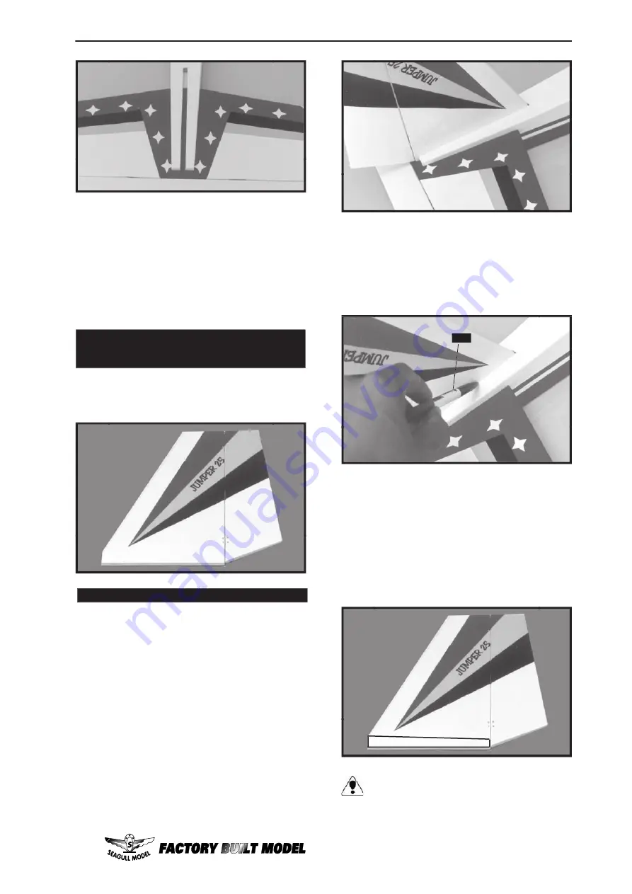
1) Using  a  modeling  knife,  remove  the 

cov er ing from over the precut hinge slot cut 

into the lower rear portion of the fuselage.  This 

slot ac cepts the low er rud der hinge.

2) Slide the vertical stabilizer into the slot 

in the top of the fu se lage.  The rear edge of 

the sta bi liz er  should be fl ush with the rear 

edge  of  the  fu se lage  and  the  lower  rudder 

hinge should engage the precut hinge slot in 

the lower fu se lage.  The bottom edge of the 

stabilizer should also be fi rmly pushed against 

the top of the hor i zon tal stabilizer.

3) While  holding  the  vertical  stabilizer 

fi rm ly in place, use a pen and draw a line on 

each side of the ver ti cal sta bi liz er where it 

meets the top of the fuselage.

4) Remove  the  stabilizer.    Using  a 

mod el ing  knife,  re move  the  cov er ing  from 

below the lines you drew.  Also re move the 

cov er ing from the bot tom edge of the stabilizer 

and  the  bottom  and  top  edges  of  the  fi ll er 

block.    Leave  the  cov er ing  in  place  on  the 

sides of the fi ller block.

When  cutting  through  the  covering  to 

re move it, cut with only enough pres sure 

to  only  cut  through  the  covering  it self.  

Cut ting into the balsa struc ture may weak en 

it.

Summary of Contents for JUMPER 25

Page 1: ..._ 2 5kg Recommended engine size___0 25 0 32 cu ins 2 stroke Recommended R C_____________ 4 channel minimum Flying skill level __________________ High wing Trainer Kit features Ready made minimal assembly finishing required Ready covered including decals trim covering Factory installed pushrod Factory installed metal engine mount Factory pinned glued control surface hinges for ultimate safety Compr...

Page 2: ...roperty WHEN YOU FLY THIS AEROPLANE YOU ASSUME ALL RISK RESPONSIBILITY If you are inexperienced with basic R C flight we strongly recommend you contact your R C supplier and join your local R C Model Flying Club R C Model Flying Clubs offer a variety of training procedures designed to help the new pilot on his way to successful R C flight They will also be able to advise on any insurance and safet...

Page 3: ...nd acetone Do not let thesechemicalscomeincontactwiththe colours on the covering and the plastic parts WING ASSEMBLY NOTE We highly recommend using 30 minute epoxy as it is stronger and provides more working time allowing the builder toproperlyaligntheparts Usingfastcure epoxywhenjoiningthewinghalvescould 2 Test fit the dihedral brace into each wing half The brace should slide in easily up tothece...

Page 4: ...LING THE AILERON SERVO MOUNT 1 Plywood Aileron Servo Mount 1 Install the rubber grommets and brass collets onto the aileron servo Test fit the servo into the aileron servo mount Because the size of servos differ you may need to adjust the size of the precut opening in the mount The notch in the sides of the mount allow the servo lead to pass through 2 Remove the aileron servo Place the mount onto ...

Page 5: ...orque rod Thread the horns on until they are flush with the ends of the torque rods 2 Thread one nylon clevis at least 5 16 onto each of the two 2mm x 170mm threaded wires 5 Slide the pushrod wires following picture bellow before installing the screws This will prevent the wood from splitting 6 With both the aileron servo and the ailerons centered 3 With the aileron servo centered install the serv...

Page 6: ...qual distance from the inside and outside ends of the wire 4 Using the two landing gear straps as a guide mark the locations of the four 3mm x 12mm mounting screws onto the fuselage surface 5 Remove the two straps and the gear wire Drill four 3 32 pilot holes into the wing for the wood screws INSTALLING THE MAIN GEAR WHEELS 8 Slide one wheel collar with 3mm x 6mm set screw onto each axle Push the ...

Page 7: ...LLATION PARTS REQUIRED q 1 Nose gear q 1 Steering arm q 1 Connector q 1 Wheel TOOLS REQUIRED Installing steering arm as follow Adjust the nose gear steering arm until the arm is parallel with the fire wall Slide one 60mm diameter wheel onto each axle and push them up against the wheel collars Slide the remaining wheel collars with 3mm x 6mm set screws onto the axles Push them up against the wheels...

Page 8: ...ube When the stopper assembly is installed in the tank the top of the vent tube should rest just below the top surface of the tank It should not touch the top of the tank 4 Test fit the stopper assembly into the tank It may be necessary to remove some of the flashing around the tank opening using a modeling knife If flashing is present make sure none falls into the tank 5 With the stopper assembly...

Page 9: ... 2 Feed both lines through the fuel tank compartment and through the predrilled hole in the firewall Pull the lines out from behind the engine while guiding the fuel tank into place Push the fuel tank until the front of the tank touches the firewall Blow through one of the lines to ensure the fuel lines have not become kinked inside the fuel tank compartment Air should flow through easily silicon ...

Page 10: ...hey can be moved if needed 9 Attach the Z Bend in the pushrod wire to the throttle arm on the carburetor You will need to remove the throttle arm from the car buretor to be able to attach the Z bend When complete reattach the throttle arm to the car buretor 10 Locate the fuel tank assembly you built earlier Connect two lengths of fuel line not in cluded to the tubes coming out of the tank Keep tra...

Page 11: ...the side of the fuselage through the hole you drilled Switch Some switches come with a hole drilled through the switch tab for this very purpose If your switch does not remove the switch and drill a 3 32 hole through the middle of the switch tab INSTALLING THE FUSELAGE SERVOS 4 Install the rubber grommets and brass collets onto the elevator rudder and throttle servos Test fit the servos into the p...

Page 12: ...en that is aligned hold the stabilizer in that position using T pins or masking tape Align the horizontal stabilizer with the wing When viewed from the rear the horizontal stabilizer should be level with the wing If it is not level use sandpaper and sand down the high side of the stabilizer mounting platform until the proper alignment is achieved The tips of the stabilizer should also be equal dis...

Page 13: ...he rear edge of the stabilizer should be flush with the rear edge of the fuselage and the lower rudder hinge should engage the precut hinge slot in the lower fuselage The bottom edge of the stabilizer should also be firmly pushed against the top of the horizontal stabilizer 3 While holding the vertical stabilizer firmly in place use a pen and draw a line on each side of the vertical stabilizer whe...

Page 14: ...orns three nylon control horn backplates and six 2 x 15mm machine screws 2 Position the two elevator horns on the bottom side of each elevator 1 1 8 out from the sides of the fuselage The clevis attach ment holes should be positioned over the hinge line Control Horn Mounting Screws Mounting Plate 3 Using a modeling knife remove the cov ering from over the two precut pushrod slots one on left side ...

Page 15: ...tor and rudder servo arms should be perpendicular to the servos 7 One at a time hold the pushrods in po sition over the respective servos to check for proper servo direction If any servo turns in the wrong direction switch your radio s reversing switches as necessary to achieve the correct direction 8 Insert the nose gear pushrod wire through the adjustable servo connector on the rudder servo arm ...

Page 16: ...bilizer using a rubber band and a modified servo arm See picture as follow Antenna Antenna Rubber Rubber Rubber Band Modified Modified Servo Arm Servo Arm Cut Cut 1 It is critical that your airplane be balanced correctly Improper balance will cause your plane to lose control and crash The center of gravity is located 7cm back from the leading edge of the wing at the fuselage sides Balance the Jump...

Page 17: ...ease the amount of throw FLIGHT PREPARATION 1 Check the operation and direction of the elevator rudder ailerons and throttle A Plug in your radio system per the manufacturer s instructions and turn everything on B Check the elevator first Pull back on the elevator stick The elevator halves should move up If it they do not flip the servo reversing switch on your transmitter to change the direction ...

Page 18: ...ying 2 Check every bolt and every glue joint in the PC 9 to ensure that everything is tight and well bonded We wish you many safe and enjoyable flights with your Jumper 25 8 Properly balance the propeller An out of balance propeller will cause excessive vibration which could lead to engine and or airframe failure 3 Double check the balance of the airplane Do this with the fuel tank empty 4 Check t...

Page 19: ...cu ins 2 stroke _____________________________0 52 cu ins 4 stroke Recommended R C_____________ 4 channel minimum Flying skill level __________________ Low wing Trainer Kit features Ready made minimal assembly finishing required Ready covered including decals trim covering Factory installed pushrod Factory installed metal engine mount Factory pinned glued control surface hinges for ultimate safety ...

Page 20: ...______ 4 channel minimum Flying skill level ______________Intermediate advanced Kit features Ready made minimal assembly finishing required Ready covered including decals trim covering Factory installed pushrods Factory installed metal engine mount Factory pinned glued control surface hinges for ultimate safety Comprehensivehardwarepackincludingwheels tank spats undercarriage spinner Photo illustr...

Page 21: ... 4240cm2 Recommended engine size ________ 0 46 0 61 cu ins 2 stroke Recommended R C __________________ 4 channel minimum Flying skill level __________________ Intermediate advanced Kit features Ready made minimal assembly finishing required Ready covered including decals trim covering Factory installed pushrods Factory installed metal engine mount Factory pinned glued control surface hinges for ul...

Page 22: ...___________________ 91 120 cu ins 4 stroke Recommended R C_____________ 4 channel minimum Flying skill level ______________Intermediate advanced Kit features Ready made minimal assembly finishing required Ready covered including decals trim covering Factory installed pushrods Factory installed metal engine mount Factory pinned glued control surface hinges for ultimate safety Comprehensivehardwarep...

Page 23: ... the photographs If yes please explain o Yes o No Were any of the kit parts o Damaged o Wrong Size o Missing o Wrong Shape If you checked any of the boxes above did you contact our Customer Service Department to resolve the problem o Yes o No Was any of the assembly difficult for you If yes please explain What did you like most about this kit o Assembly Manual o Parts Fit o Hardware Supplied o Pri...

Page 24: ...thout proper postage Please return this sheet to Europe J Perkins Distribution Limited 90 96 Greenwich High Road London SE10 8JG England Fax 0044 208 692 2469 Please return this sheet to Australia Model Engines 44 Downing Street Oakleigh Melbourne 3166 Australia Fax 03 9569 0930 ...

Reviews: