SD-MA-029
9
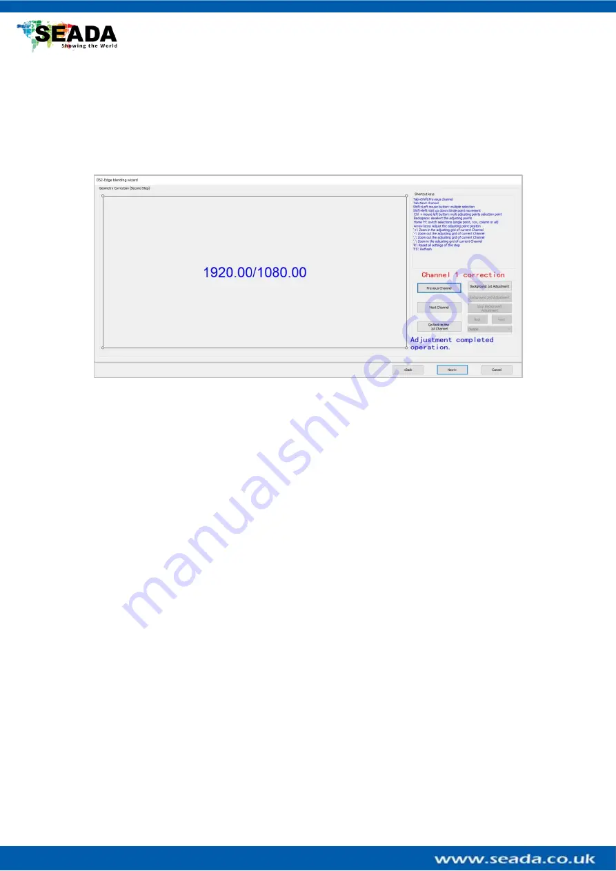
4.2.2 Geometry Correction (edge blending Step 2)
First, the software shows the first output channel with grid of 1920x1080 (default, users can
change at
chapter ‘4.1
Output Resolution Setting
’)
and it will be displayed onto the wall as
well. Users can use mouse scroll wheel
or hotkeys of ‘+’ and ‘
-
‘to
change the size of the grids
of current channel.
The 2
nd
output will show in different colour grid. users can use comma
‘
,
’ or ‘.’
on control PC
keyboard to zoom in/out the grids.
User hotkeys below to help the adjustment.
Hotkeys:
Ctrl + mouse left click: multi adjusting points selection point by point
Ctrl + allow keys: multi adjusting points selection point by point
Shift + mouse left drag: multi adjusting points selection in group
Shift + allow keys: to switch to next adjusting point
‘
-
’:
Zoom out the adjusting grid of current Channel
‘+’
: Zoom in the adjusting grid of current Channel
‘.’: Zoom out the adjusting grid of adjacent Channel
‘,’: Zoom in the adjusting grid of adjacent Channel
Arrow keys: Adjust the adjusting point position
Backspace: deselect the adjusting points
‘F5’: Refresh
‘H’: switch selections (single point, row, column or all)
‘R’: Reset all settings of this step


