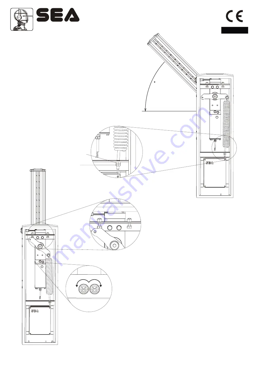
Fig. 14
Fig. 15
5
4
5
4
9) Force adjustment
If necessary the force of thrust of the beam can be
adjusted through the two calibration screws (grey and
yellow) placed on the side of the hydraulic unit
(Fig.16).
*The automation is adjusted at 15 kg force ex works
so to guarantee the anti-crush safety. We recommend
to adjust it only in case of necessity.
Fig.16
-
+
English
8) Beam balancing
-
Release the beam with manual release, so that it is
free to be opened and closed manually (Fig.18).
-
Place the beam at approx. 45°.
-
Loosen or tighten the spring stretching nut until the
spring counterbalances the weight of the 45° beam
(Fig. 14). The best balancing position is obtained when
the beam reaches the position shown in Fig. 14.
-
After having obtained the balancing, lock the nuts of
the spring stretcher with the counter nut and re-block
the motor.
Spring
nut
stretching
Anchoring
lock nut
10) Beam levelling
Note:
this operation must be carried out only if the beam is not
perfectly horizontal (closing stage) or vertical (opening stage) at
the end of its stroke.
-
Release the beam with the special manual release so that it is
free to open and close manually.
-
Release the screws of the limit switch on unscrewing the nuts
on the mechanical stops (fig.15).
-
Loosen or tighten the stop screws so that the beam is released
in its vertical position (opening stage) and horizontal position
(closing stage) (Fig. 15).
-
After having executed the levelling lock the screws of the limit
switch tightening the nuts on the mechanical stops and re-lock
the beam.
Sistemi Elettronici
di Apertura Porte e Cancelli
International registered trademark n. 804888
®
Cod. 67410035 Rev 06 - 06/2010
23


