English
11)
Electrical system
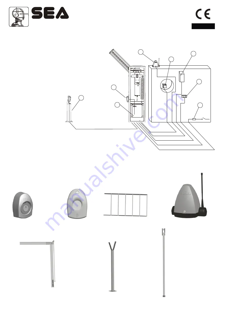
Fig. 17 sketches the electrical system that the barrier requires.
The two numbers located near the electrical cables indicate the cable number and section.
Captions:
1- GATE 1 electronic control unit
2- Transmitting photocell (Ghost 40)
3- Receiving photocell (Ghost 40)
4- Key switch (Key Plus)
5- Radio receiver
6- Flashing light (Flash)
7- Push-button station
8- Differential switch
Sistemi Elettronici
di Apertura Porte e Cancelli
International registered trademark n. 804888
®
1
1
2
2
4
4
5
5
6
6
7
7
8
8
2x1
2x1
2x1
4x1
3x1,5
3x1
Fig.17
3
3
3x1
GHOST 40 - GHOST 50
ACCESSORIES
FOR
VELA
* FORK SUPPORT
* FEXLIBLE SUPPORT
(ONLY BEAM)
* it is reccommended to mount with beams which are longer than 3 m.
SKIRT
ARTICULATED BEAM
KEY SWITCH
WARNING LAMP
Cod. 67410035 Rev 06 - 06/2010
24


