background image

Sistemi elettronici
di Aperture Porte e Cancelli

Fig. 14

Fig. 15

Adjusting the trimmer for braking, placed on the electronic 
control unit, it is possible to make the gate stop on the desired 
position.

Fig. 18

8. GROUNDING (Fig. 18)

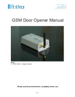
9. CLUTCH ADJUSTMENT 

(Saturn 1000 and 2000)

9.1.

Switch off electric power.

9.2.

In order to adjust the clutch it is necessary to:

- Act on the scrub screw “A” (Fig. 19) as follows:
- Turning clockwise = less clutch sensibility / more thrust force
-Counter clockwise = more clutch sensibility / less thrust force
.

A

A

Fig. 19

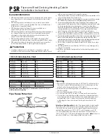
Mechanical limit switch

Inductive limit switch

4/30

7. LIMIT SWITCH ADJUSTMENT

7.1.

 In order to install and adjust the limit switch in opening, follow 

the below mentioned instructions (Fig. 13):
- Take the gate to complete opening,
- Place the small plate on the gear rack so that the limit switch is   
(small lever in case of mechanical limit switch (Fig. 14); small 
pointers   placed on the upper part in case of inductive limit switch 
(Fig. 15)) in corrispondence of pointX which is placed 50 mm   
from the folded side of the small plate (fig. 16) and fix it with the 
delivered screws   (Fig. 17).

7.2.

 In order to install and adjust the limit switch in closing, follow 

the below mentioned   instructions (Fig. 13):
- Take the gate to complete closing 
- Place the small plate on the gear rack so that   the limit switch is 
in corrispondence of pointX which is placed 50 mm from the 
folded side of the small plate (fig. 16) and fix it with the delivered 
screws (Fig. 17).

Fig. 13

Limit switch in closing

Limit switch in opening

Fig. 17

50 mm

X

Fig. 16

Position in which must be the spring 
(mechanical limit switch) or the 
pointer (inductive limit switch) 

+ power

- sensibility

- power

+ sensibility

cod. 67410325

REV 01 - 04/2007

ENGLISH

Summary of Contents for Saturn 1000

Page 1: ...ree Pinion Z16 Z20 speed Maximum torque Gate maximum weight Mechanical clutch Inductive or mechanical limit switch 230 V 5 50 60 Hz 330W 550W 750W 1 6 A 2 6 A 3 0 A 16 uf 12 5 uf 25 uf 35 35 30 20 C 55 C 150 C 12 Kg 13 Kg 14 5 Kg Electronic Electronic Mechanical IP55 9 5 11 m min 30 Nm 55 Nm 70 Nm 600 Kg 1000 Kg 2000 Kg no with or without yes 600 1000 2000 8 8 9 9 1 1 3 3 6 6 2000 Kg 1800 Kg 1000 ...

Page 2: ...on plate it is necessary to 2 1 Prepare a concret basement with the dimensions shown in Fig 1 where the foundation plate and the anchor bolts will be concreted NOTE It is recommended gate structure permitting to lift the foundation plate about 50mm from the ground in order to avoid eventual water stagnation Fig 1 2 30 43 58 Fig 3 Fig 5 4 FITTING OF THE MOTOR REDUCER 4 1 Insert the 4 grains into th...

Page 3: ...on the toothed pinion of the motor so that it results parallel to the ground slideway of the gate place it as shown in Fig 9 and electrically weld the central pawl B to the gate structure Fig 10 6 4 Make sure that all the gear rack elements are perfectly aligned and placed correctly teeth in phase It s suggested to place two aligned elements infront of a third one as shown in Fig 11 6 5 Repeat the...

Page 4: ...Place the small plate on the gear rack so that the limit switch is small lever in case of mechanical limit switch Fig 14 small pointers placed on the upper part in case of inductive limit switch Fig 15 in corrispondence of pointX which is placed 50 mm from the folded side of the small plate fig 16 and fix it with the delivered screws Fig 17 7 2 In order to install and adjust the limit switch in cl...

Page 5: ...not being used This is a quotation from the GENERAL DIRECTIONS that the installer must read carefully before installing Packaging materials such as plastic bags foam polystyrene nails etc must be kept out of children s reach as dangers may arise The electrical installation shall be carried out by a professional technician who will release documentation as requested by the laws in force D L 46 90 F...

Page 6: ... run mains carrying cables in separate ducts to low voltage control cables to prevent mains interference INTENDED USE The SATURN operator has been designed to be solely used for the automation of sliding gates SPARE PARTS To obtain spare parts contact SEAs r l Zona Ind le 64020 S ATTO Teramo Italia SAFETYAND ENVIRONMENTALCOMPATIBILITY Don t waste product packing materials and or circuits When bein...

Reviews: