3. RELEASING SYSTEM OF THE OPERATOR
3.1.
To release the operator follow the instruction below
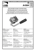
1. put the red T-shaped release key into the hexagonal hole as in Fig. 27
2. turn the release key of 90° toward right or left until it stops without forcing (Fig. 28).
Fig. 29
3.2.
To lock the actuator again bring the line in the horizontal position through the release key (Fig. 27) and move the leaf manually
until the clutch of the automation.
RISK EXAMINATION
The points pointed by arrows in
. 29 are potentially dangerous. The installer must take a thorough risk examination to prevent
crushing, conveying, cutting, grappling, trapping so as to guarantee a safe installation for people, things and animals (
).
Fig
Re. Laws in
force in the country where installation has been made.
NOTICE
SEA s.r.l can not be deemed responsible for any damage
or accident caused by product breaking, being damages or
accidents due to a failure to comply with the instructions
herein. The guarantee will be void and the manufacturer
responsibility (according to Machine Law) will be nullified if
SEA Srl original spare parts are not being used.
This is a quotation from the
GENERAL DIRECTIONS that the installer must read
carefully before installing.
Packaging materials such as plastic bags, foam
polystyrene, nails etc must be kept out of children’s reach
as dangers may arise.
The electrical installation shall be carried out by a
professional technician who will release documentation as
requested by the laws in force.
1
2
Fig. 27
Fig. 28
Line in
horizontal position:
Operator locked
Line in
vertical position:
Operator released
90°
90°
ALPHA
16
International registered trademark n. 2.777.971
REV 03 - 06/2009
MECHANICAL INSTALLATION


