


9711QOR-86 C & Ku-Band TXRX
Installation
3-33
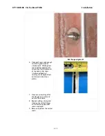
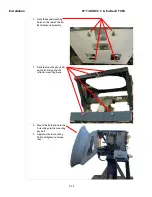
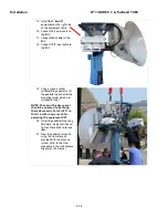
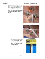
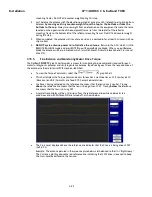
5.
Use wedges to lift the upper panels off
of the lower panels about ½”.
6.
Install a good bead of caulking
between the bottom of the upper
panels and the top of the lower panels
tighten all of the bolts in that seam
(smaller dual beads of caulking can be
applied from outside and inside if you
prefer). Remove the wedges and
radome lifting brackets, and then firmly
tighten all the bolts.
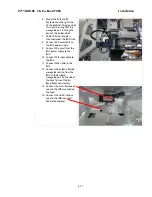
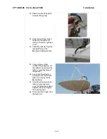
7.
Remove the tape from the upper and
lower panels. All tape should now be
removed from the radome.
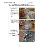
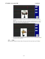
8.
The ADE Assembly is now
complete, ready for web straps to
be attached for lifting the ADE
onto the ship.
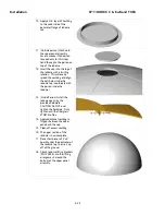
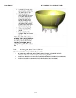
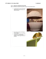
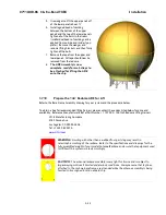
3.7.10.
Prepare the 144” Radome ADE for Lift
Refer to the Base Frame Assembly drawing for your system and the procedure below.
To obtain a Sea Tel recommended lifting harness, please contact the vendor listed below for price and
availability. Reference Manufacturer/Sea Tel Part Number: 119792-A 144 Inch Radome Lifting Harness:
Lift-It Manufacturing Company
4780 Corona Ave.
Los Angeles, CA 90055-3808
Tel: +1 323 582 6076
www.Lift-it.com
WARNING:
Hoisting with other than a webbed four-part sling may result in
catastrophic crushing of the radome. Refer to the specifications and drawings for the
fully assembled weight of your model Antenna/Radome and assure that equipment used
to lift/hoist this system is rated accordingly.
CAUTION:
The antenna/radome assembly is very light for its size and is subject to
large swaying motions if hoisted under windy conditions. Always ensure that tag lines,
attached to the radome base frame, are attended while the antenna assembly is being
hoisted to its assigned location aboard ship.
Summary of Contents for 9711QOR-86
Page 4: ......
Page 14: ...Table of Contents xiv This Page Intentionally Left Blank ...
Page 26: ...Site Survey 9711QOR 86 C Ku Band TXRX 2 8 This Page Intentionally Left Blank ...
Page 70: ...Installation 9711QOR 86 C Ku Band TXRX 3 44 This Page Intentionally Left Blank ...
Page 74: ...Basic Setup of the ACU 9711QOR 86 C Ku Band TXRX 4 4 This Page Intentionally Left Blank ...
Page 78: ...Setup Ships Gyro Compass 9711QOR 86 C Ku Band TXRX 6 2 This Page Intentionally Left Blank ...
Page 80: ...Setup Band Reflector Select 9711QOR 86 C Ku Band TXRX 7 2 This Page Intentionally Left Blank ...
Page 86: ...Setup Home Flag Offset 9711QOR 86 C Ku Band TXRX 9 4 This Page Intentionally Left Blank ...
Page 90: ...Setup Targeting 9711QOR 86 C Ku Band TXRX 10 4 This Page Intentionally Left Blank ...
Page 96: ...Setup Searching 9711QOR 86 C Ku Band TXRX 11 6 This Page Intentionally Left Blank ...
Page 122: ...Antenna Specific Operation 9711QOR 86 C Ku Band TXRX 16 12 This Page Intentionally Left Blank ...
Page 126: ...Functional Testing 9711QOR 86 C Ku Band TXRX 17 4 This Page Intentionally Left Blank ...
Page 190: ...Drawings 9711QOR 86 C Ku Band TXRX 23 2 This Page Intentionally Left Blank ...
Page 196: ......
Page 199: ......
Page 233: ......
Page 234: ......
Page 239: ......
Page 241: ......
Page 243: ......