


9711QOR-86 C & Ku-Band TXRX
Installation Troubleshooting
18-5
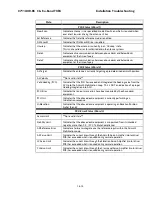
Level cage/Level PCB alignment Verification
(sensor alignment)
DISPV (Ref)
Targeting
Stabilization
Rate Sensor Output Verification
DISPW (Rate)
Stabilization
Level and CL fine balance Verification
DISPTC (Drive)
Stabilization
AZ Friction Torque Test
DISPTC (Drive)
Stabilization
DishScan® Drive/Phase
DishScan® XY
Tracking
Stabilization
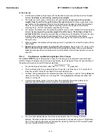
18.3.4.
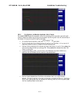
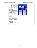
Antenna Loop Error Monitoring
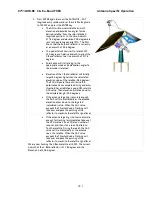
The DacRemP DISPIVC graph chart provides a means for monitoring the accumulated velocity errors of the
antenna for diagnostic purposes. If this error is excessive, it indicates external forces are acting on the
antenna. These forces may be the result of but not restricted to static imbalance, excessive bearing friction,
cable binding, or wind loading. If these forces cause the antenna to mis-point by more than 0.5° from the
desired position the PCU will flag a “Stab Limit” error.
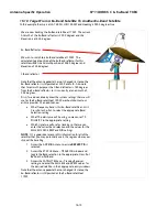
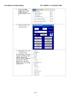
•
To view the position error, select the
graph chart.
•
This chart displays sensed axis errors via three traces, CL (Cross Level), LV (Elevation), and AZ
(Azimuth), at a fixed 0.05
º
/ vertical division.
•
The normal trace average will plots it’s display
±
3 divisions from the red reference line. Any trace
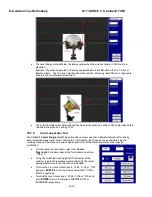
line average plotted above this is of concern and troubleshooting required. The example below
shows the forces exerted onto the antenna as a resultant of DishScan® Drive. The example below
shows the results of various forces put upon antenna.
Summary of Contents for 9711QOR-86
Page 4: ......
Page 14: ...Table of Contents xiv This Page Intentionally Left Blank ...
Page 26: ...Site Survey 9711QOR 86 C Ku Band TXRX 2 8 This Page Intentionally Left Blank ...
Page 70: ...Installation 9711QOR 86 C Ku Band TXRX 3 44 This Page Intentionally Left Blank ...
Page 74: ...Basic Setup of the ACU 9711QOR 86 C Ku Band TXRX 4 4 This Page Intentionally Left Blank ...
Page 78: ...Setup Ships Gyro Compass 9711QOR 86 C Ku Band TXRX 6 2 This Page Intentionally Left Blank ...
Page 80: ...Setup Band Reflector Select 9711QOR 86 C Ku Band TXRX 7 2 This Page Intentionally Left Blank ...
Page 86: ...Setup Home Flag Offset 9711QOR 86 C Ku Band TXRX 9 4 This Page Intentionally Left Blank ...
Page 90: ...Setup Targeting 9711QOR 86 C Ku Band TXRX 10 4 This Page Intentionally Left Blank ...
Page 96: ...Setup Searching 9711QOR 86 C Ku Band TXRX 11 6 This Page Intentionally Left Blank ...
Page 122: ...Antenna Specific Operation 9711QOR 86 C Ku Band TXRX 16 12 This Page Intentionally Left Blank ...
Page 126: ...Functional Testing 9711QOR 86 C Ku Band TXRX 17 4 This Page Intentionally Left Blank ...
Page 190: ...Drawings 9711QOR 86 C Ku Band TXRX 23 2 This Page Intentionally Left Blank ...
Page 196: ......
Page 199: ......
Page 233: ......
Page 234: ......
Page 239: ......
Page 241: ......
Page 243: ......