


Introduction
9711QOR-86 C & Ku-Band TXRX
1-2
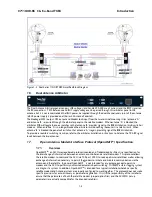
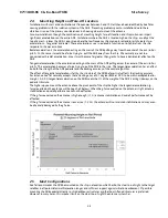
Figure 1 -1 Series 11QOR TXRX Simplified Block Diagram
1.5.
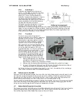
Dual Antenna Configuration
Sometimes, due to very large blockage conditions, you may need to install a dual antenna configuration to provide
uninterrupted services. Two full antenna systems are installed and the ACU control outputs are connected to an
arbitrator switch panel which then is connected to the below decks equipment. NOTE: The RXIF from EACH antenna
MUST be connected to the RF IN (J6) on the rear panel of its respective ACU then RFOUT (J7) is connected to the RXIF
input of the Dual Antenna Arbitrator. This connection scheme is required for ACU “A” to be able to control Antenna
“A” (and ONLY Antenna “A”) AND ACU “B” to be able to control Antenna “B” (and ONLY Antenna “B”).
You will program the blockage zone(s) for each of the two antennas (refer to Setup – Blockage Zones). The blockage
output from the ACU is fed to the Terminal Mounting Strip so that the output of each ACU can be connected to the
arbitrator panel to control it. The blockage output is available on SW2 terminal of the Terminal Mounting Strip to
provide a transistor “short” to ground when the antenna is within a blockage zone programmed into the ACU. When
not blocked the SW2 terminal will be an “open”.
When one antenna is blocked, its blockage output will command the arbitrator panel to switch services to the modem
from that antenna to the other antenna. The arbitrator panel provides a logic latch to prevent excess switching when
the ship heading is yawing, therefore, causing if the antenna to be repeatedly blocked – unblocked – blocked.
Summary of Contents for 9711QOR-86
Page 4: ......
Page 14: ...Table of Contents xiv This Page Intentionally Left Blank ...
Page 26: ...Site Survey 9711QOR 86 C Ku Band TXRX 2 8 This Page Intentionally Left Blank ...
Page 70: ...Installation 9711QOR 86 C Ku Band TXRX 3 44 This Page Intentionally Left Blank ...
Page 74: ...Basic Setup of the ACU 9711QOR 86 C Ku Band TXRX 4 4 This Page Intentionally Left Blank ...
Page 78: ...Setup Ships Gyro Compass 9711QOR 86 C Ku Band TXRX 6 2 This Page Intentionally Left Blank ...
Page 80: ...Setup Band Reflector Select 9711QOR 86 C Ku Band TXRX 7 2 This Page Intentionally Left Blank ...
Page 86: ...Setup Home Flag Offset 9711QOR 86 C Ku Band TXRX 9 4 This Page Intentionally Left Blank ...
Page 90: ...Setup Targeting 9711QOR 86 C Ku Band TXRX 10 4 This Page Intentionally Left Blank ...
Page 96: ...Setup Searching 9711QOR 86 C Ku Band TXRX 11 6 This Page Intentionally Left Blank ...
Page 122: ...Antenna Specific Operation 9711QOR 86 C Ku Band TXRX 16 12 This Page Intentionally Left Blank ...
Page 126: ...Functional Testing 9711QOR 86 C Ku Band TXRX 17 4 This Page Intentionally Left Blank ...
Page 190: ...Drawings 9711QOR 86 C Ku Band TXRX 23 2 This Page Intentionally Left Blank ...
Page 196: ......
Page 199: ......
Page 233: ......
Page 234: ......
Page 239: ......
Page 241: ......
Page 243: ......