Procedure, Radome Strain Relief Installation
Page 1 of 6
Document No
131226 Rev A
Form # 117140-B
1.0
Purpose. To define the installation procedure for installing strain reliefs in “smooth base”
radomes.
2.0
Scope. This installation procedure applies to fiberglass radomes having Sea Tel’s standard
four-hole mounting pattern, and M12 mounting hardware
3.0
Tools/materials.
, in the 80-180 cm (34-66 in)
nominal size range, typically referred to as “smooth” base radomes. It also applies to our
larger 193 cm (76-inch) radome having a twelve-hole mounting pattern. It is to be used where
the preferred center cable exit may not be desired.
1.
Electric drill.
2.
Small drill bit 1/8” dia. (3-4mm dia.).
3.
Hole saw, 1 3/8” dia. (35 mm), with mandrel and ¼” dia. pilot drill.
4.
Medium file.
5.
Two 1-1/2” (38 mm) adjustable pliers.
6.
#2 Phillips screwdriver.
7.
Fiberglass resin & catalyst, (marine grade) - at least 2 oz (50 cc).
Such as Tap Plastics Marine Vinyl Ester Resin with MEKP Catalyst.
Note: Use liquid resin, instead of paste type, due to better penetration.
8.
Mixing cup – 4 oz (100 cc).
9.
Disposable brush.
10.
Strain Relief Assembly 124903-1, (one per cable).
4.0
Responsibilities. It is the responsibility of the installer to observe all standard safety
precautions, including eye, slip, and chemical protection when performing this procedure.
4.1
Procedure.
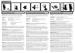
Remove the standard cable pass through assembly 130818-1*
* N/A for 193 cm (76-inch) nominal size radomes. Refer to Fig 1, then use #2 Phillips
screwdriver to remove 4 ea. attachment screws.
Fig. 1 – Cable pass-thru assembly
Use #2 Phillips
screwdriver to
remove 4 ea.
screws.
Summary of Contents for 5012-33
Page 3: ...iii RTT E Declaration Page Testing Being Conducted...
Page 4: ...iv FCC Declaration Testing Being Conducted...
Page 8: ...5012 33 Installation Manual Table of Contents viii This Page Intentionally Left Blank...
Page 20: ...5012 33 Installation Manual Site Survey 2 8 This Page Intentionally Left Blank...
Page 34: ...5012 33 Installation Manual Installation 3 14 This Page Intentionally Left Blank...
Page 44: ...5012 33 Installation Manual Setup Ship s Gyro Compass 5 4 This Page Intentionally Left Blank...
Page 54: ...5012 33 Installation Manual Setup Blockage Zones 8 2 This Page Intentionally Left Blank...
Page 64: ...5012 33 Installation Manual Quick Start Operation 10 6 This Page Intentionally Left Blank...
Page 80: ...5012 33 Installation Manual DRAWINGS 13 2 This Page Intentionally Left Blank...
Page 90: ......
Page 91: ......
Page 92: ......
Page 98: ......