


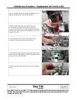


Field Service Procedure – Replacement Pol Pot Kit, 4012
Page
1
of
16
Document No
136829 Rev A
Copyright © Sea Tel, Inc 2012 - The information contained in this document is proprietary to Sea
Tel, Inc. This document may not be reproduced or distributed in any form without prior written
consent of Sea Tel, Inc.
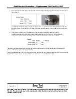
1.
Brief
Summary:
Troubleshooting
document
for
diagnosing
a
fault
with
and
replacing
the
pol
pot
on
the
4012
antenna.
2.
Checklist:
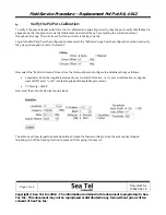
Verify
Range
of
Motion
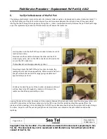
Verify
Pot
Feedback
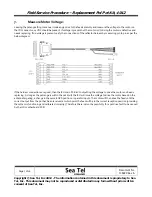
Measure
Resistance
3.
Theory
of
Operation:
A
polang
potentiometer
is
used
to
provide
a
feedback
reference
for
the
position
of
the
feed
assembly
for
linear
polarization.
The
pot
acts
as
a
potential
divider
giving
an
output
voltage
which
varies
from
0VDC
to
5VDC
throughout
the
feed
assembly’s
270
degree
range
of
motion.
The
4012
antenna
has
a
phase
card
installed
in
the
feed
horn
which
will
reflect
the
signal
meaning
for
each
0.5
degree
of
physical
rotation
of
the
feed
the
change
in
signal
will
be
1.0
degree
meaning
that
the
feed
assembly
of
the
4012
antenna
only
has
to
physically
drive
135
degrees
to
view
the
full
270
degrees
of
rotation.
The
ICU
converts
the
voltage
output
from
the
pot
into
the
numerical
value
to
align
the
feed
in
the
required
position
based
on
the
vessels
GPS
location
and
the
look
angle
to
the
required
satellite.
A
failure
with
the
pot
will
cause
it
to
output
an
incorrect
voltage
will
result
in
the
feed
assembly
not
being
aligned
correctly
causing
bad
cross
pol
isolation.
One
indication
that
there
is
a
fault
with
the
feed
alignment
of
the
system
is
that
the
target
light
will
be
permanently
illuminated
on
the
MXP
and
that
the
antenna
won’t
target
correctly.
It
will
sit
8
degrees
above
(or
8
degrees
below
at
high
elevation
look
angles)
the
satellites
elevation
look
angle.
As
part
of
the
antennas
targeting
procedure
the
system
will
target
8
degrees
above
(or
8
degrees
below
at
high
elevation
look
angles)
the
satellite,
calculate
the
auto
threshold
setting
based
on
the
noise
floor
level
and
then
align
the
feed
for
the
correct
reception
position
based
on
the
vessels
GPS
location
and
the
lookup
table.
If
the
system
is
unable
to
drive
the
pol
motor
to
obtain
the
correct
feedback,
or
if
the
pot
has
failed
and
won’t
give
the
correct
feedback,
the
antenna
can’t
complete
the
target
process
and
the
antenna
will
stay
in
this
position.
Setting
the
pol
setting
to
manual
will
make
the
antenna
target
by
removing
the
automatic
function
from
the
targeting
process;
however
the
miss
alignment
of
the
feed
will
cause
bad
cross
pol
isolation.
Summary of Contents for 4012
Page 1: ......