


Field Service Procedure – Replacement Pol Pot Kit, 4012
Page
12
of
16
Document No
136829 Rev A
Copyright © Sea Tel, Inc 2012 - The information contained in this document is proprietary to Sea
Tel, Inc. This document may not be reproduced or distributed in any form without prior written
consent of Sea Tel, Inc.
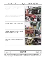
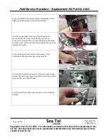
19.
Use
a
3mm
Allen
wrench
to
remove
the
2
screws
that
mount
the
pol
pot
assembly
to
the
bottom
plate
of
the
RF
cage.
Retain
the
hardware
for
future
use.
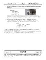
20.
Pull
the
failed
pot
foreward
and
lift
it
up
to
remove
the
defective
pol
pot
assembly.
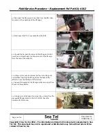
21.
Install
the
replacement
pol
pot
assembly
in
the
same
manner,
applying
Loctite
242
to
the
threads.
Do
not
fully
tighten
the
screws
at
this
time.
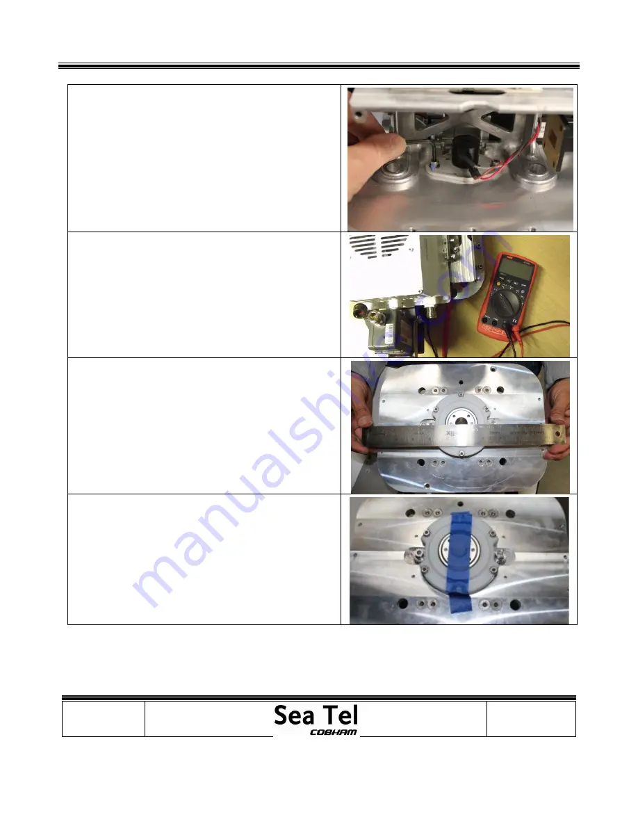
22.
Flip
the
RF
cage
over
to
expose
the
feed/motor/pot
gears.
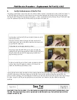
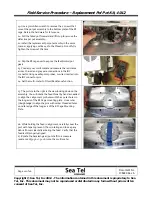
23.
Connect
your
multi
‐
meter
and
measure
the
resistance
across,
the
red
and
grey
wire
connections
in
the
IDC
connector
Using
needle
point
probes,
or
wires
inserted
into
the
IDC
connector
pins.
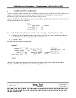
24.
Set
the
multi
‐
meter
to
Ohms/Resistance
function.
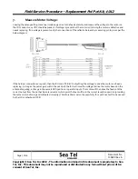
25.
The
picture
to
the
right
is
the
view
looking
down
on
the
assembly.
You
will
rotate
the
feed
throat
by
hand
as
needed
to
align
the
2
alignment
pin
holes
with
the
2
outer
holes
in
the
long
axis
of
the
RF
Cage
mounting
plate.
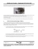
Use
a
ruler
(straightedge)
to
align
the
pins
with
center
threaded
holes
on
outer
edge
of
the
long
axis
of
the
RF
Cage
Mounting
Plate.
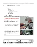
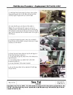
26.
While
holding
the
feed
in
alignment,
carefully
cover
the
port
with
tape
to
prevent
it
from
rotating
and
to
keep
any
debris
from
accidentally
entering
the
feed.
Verify
that
the
feed
is
still
properly
aligned.
27.
Rotate
the
backlash
gear
(pot
shaft)
to
a
measure
resistance
of
3050
+/
‐
50
ohms
on
the
multi
‐
meter.
Summary of Contents for 4012
Page 1: ......