


Field Service Procedure – Replacement Pol Pot Kit, 4012
Page
13
of
16
Document No
136829 Rev A
Copyright © Sea Tel, Inc 2012 - The information contained in this document is proprietary to Sea
Tel, Inc. This document may not be reproduced or distributed in any form without prior written
consent of Sea Tel, Inc.
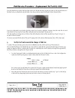
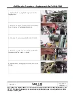
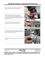
28.
Use
a
screwdriver
to
hold
the
bottom
half
of
the
backlash
gear
(pot
shaft)
steady
while
rotating
the
top
half
CW
one
tooth
(against
the
spring
action)and
push
the
pot
assmebly
forward
to
mate
into
the
driven
gear
in
the
feed.
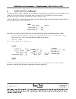
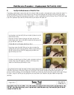
29.
Hold
tension
against
the
pot
bracket,
and
while
assuring
that
the
pot
resistance
reading
is
still
3050
+/
‐
50
ohms,
tighten
the
mounting
screws.
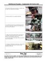
30.
If
the
pot
resistance
is
not
3050
+/
‐
50
ohms,
repeat
steps
23
‐
29
until
the
proper
reading
is
achieved
at
exact
feed
alignment.
31.
Remove
the
tape
from
the
feed
and
verify
alignment
and
resistance
when
exactly
aligned.
If
correct,
this
completes
calibration
of
the
assembly.
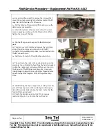
32.
Route
the
pot
wires
throught
the
RF
cage
where
they
will
not
be
pinched
when
re
‐
installing
the
side
bracket
and
install
the
harnesses
back
into
the
wrap
removed
is
step
18.
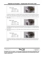
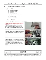
33.
Flip
the
RF
cage
over
to
expose
the
pol
motor
backlash
gear.
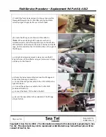
34.
Use
a
small
flat
blade
screwdriver
to
hold
the
bottom
half
of
the
backlash
gear
steady
while
rotating
the
top
half
CW
one
tooth
(against
the
spring
action)and
push
the
motor
assemebly
forward
to
mate
into
the
driven
gear
in
the
feed.
35.
Once
engaged
tighten
the
screws
securing
the
pol
motor
to
the
bottom
plate
of
the
RF
cage
using
a
3mm
Allen
wrench.
Apply
Loctite
242
to
the
threads.
*Note:
Precise
alignment
of
the
feed
is
not
required
when
re
‐
coupling
the
motor.
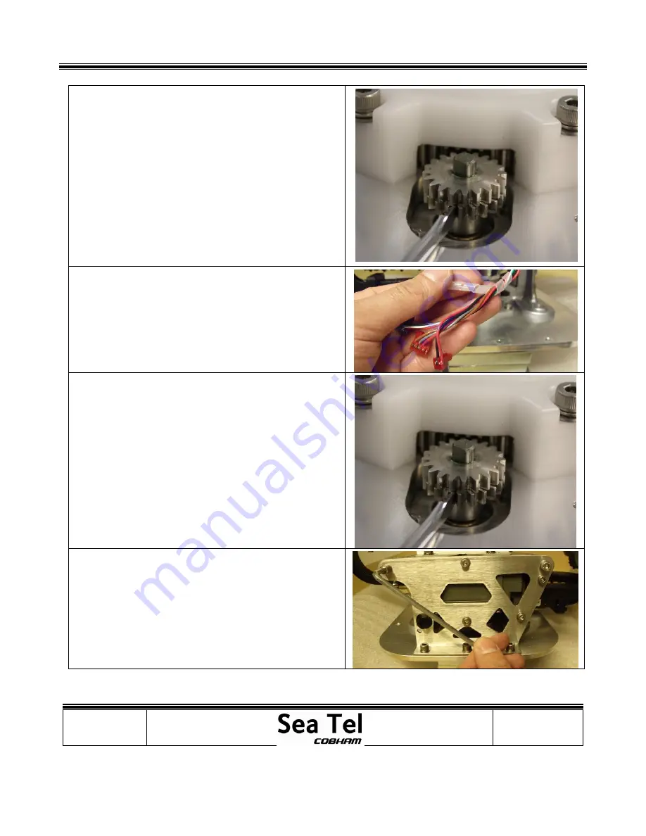
36.
Install
the
Co
‐
Pol
LNB
and
bracket
assembly
to
the
RF
cage
using
a
the
5
screws
removed
in
step
15
and
a
4mm
Allen
wrench.
Apply
Loctite
242
to
the
threads,
do
not
fullt
tighten
at
this
time.
*Note:
Ensure
the
waveguide
bracket
is
installed
on
the
outside
of
the
flange
so
the
5
mounting
points
align
correctly.
Summary of Contents for 4012
Page 1: ......