


Version 1 .0
| 13
6 .1 .2
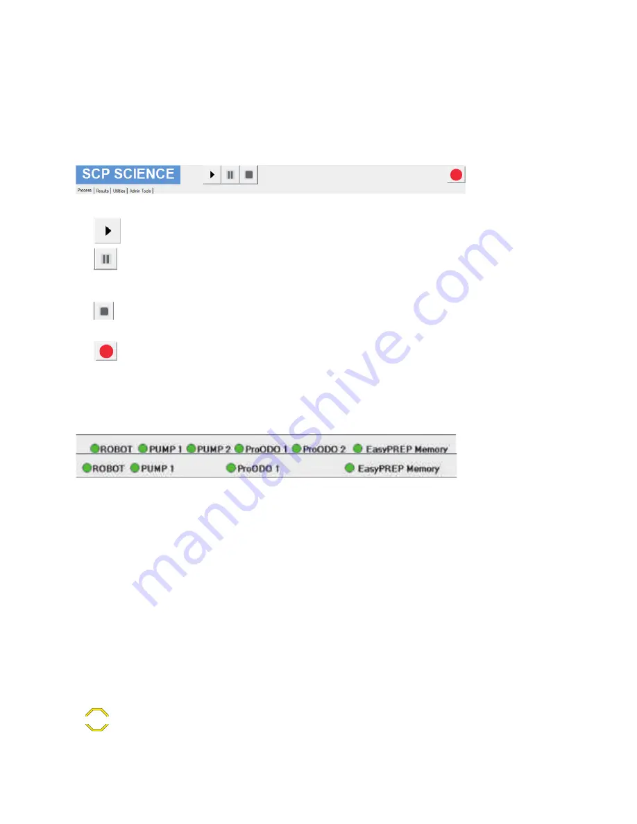
Operational Buttons
There are four (4) buttons on the title bar, as shown below.
Figure 5. Four buttons to control the test progress
•
“Run” button is blue when enabled and grey when disabled.
•
“Pause” button is blue when enabled and grey when disabled. It will show as “Resume” after being pressed. When resumed, the
sequence will continue from the break point. The pause will only take place once the commands in the que are completed. This may
take up to 1 minute to complete.
•
“Stop” button goes red when enabled and grey when disabled. When the sequence is interrupted, the test will stop after the current
action is finished and the result table is displayed. If the “Run” button is pressed again, the sequence will restart from the beginning.
•
"Emergency stop". The system stops completely. The software needs to be closed before restarting the tests.
6.1.3 Hardware Detection
Figure 6. indicators to show the status of communication with hardware.
The six (6) for dual probe configuration and 4 for single probe configuration indicators at the bottom of the screen indicate whether the
modules have been detected by the instrument. A red indicator signifies that a module has not been detected or is faulty. A green indicator
signifies that the module has been detected and is ready for use.
ROBOT
indicator is for the robotic system.
ProODO #1
indicator is for the first BOD Probe.
ProODO #2
indicator is for the second BOD Probe.
Pump 1
indicator is green to indicate that the software is communicating with the Pump module for the first BOD Probe.
Pump 2
indicator is green to indicate that the software is communicating with the Pump module for the second BOD Probe.
EasyPREP
Memory
indicator is green to indicate that the software is communication with the on board computer.
If the indicator remains red after start up, go to the Troubleshooting section (Section 10, page 39).
CAUTION


