


Page 50
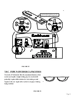
7.8 PIPE NOTCHER
The Pipe Notcher is a component tool designed to saddle cut pipe or tubing for applications such as
railings. There are notchers available to notch angles in pipe and tubing, also. For prices and
availability, contact your local dealer or the factory.
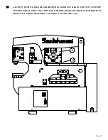
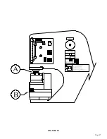
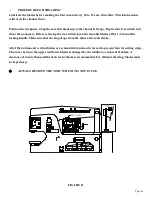
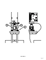
7.8A PIPE NOTCHER INSTALLATION
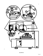
SEE FIGURE 22 ON THE FOLLOWING PAGE.
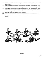
The pipe notcher can be installed in either the punch station or under the upper arm. When installed on
the tool table, the selector switch must be in the SHEAR position. When installed in the punch station, the
selector switch must be in the PUNCH position. When INSTALLING THE NOTCHER IN THE PUNCH
STATION, 1. Remove the die holder and the stripper. 2. Install the pusher (F) on the punch ram, using
the #45 punch retaining nut (C)NOTE: The upper and lower dies have an alignment pin and groove in
them to prevent mismatching sizes. Make sure that the dies you have selected are a matched set before
installing them. 3. Set the notcher on the bolster and align the slug hole in the notcher with the hole in the
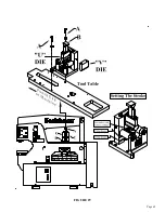
bolster. 4. Anchor the tool with the M16 bolt (D) provided. To MOUNT THE NOTCHER ON THE
TOOL TABLE, 1. Attach the riser (B) and the pusher (E) to the tool using the two M10 x 60 bolts and
lock washers. 2. Align the tool over the "D" shaped slug hole in the tool table (as shown) and bolt it down
to the tool table with the M-12 bolt (G) provided.3. Both the 6 x 6 Angle Shear and the Pipe Notcher can
be used on the tool table at the same time.
CAUTION: With the tool mounted in either station, it is
necessary to set the down stroke of the machine to prevent damage to the tool. The upper die should not
pass the lower die by more than1/32 of an inch (.7mm).
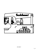
7.8B PIPE NOTCHER OPERATION
To achieve the best results from your unit, PLEASE OBSERVE THESE SIMPLE RULES:
1..
Keep the unit clean. Whenever dirt or metal chips accumulate, remove the 8mm limit screw
located in the center at the rear of the punch. Lift out the punch-holder and the two springs
(1/2 x 3"). Clean the unit with solvent.
2.
CAUTION: DO NOT DIASSEMBLE THE UPPER PUNCH.
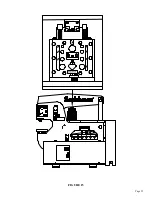
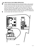
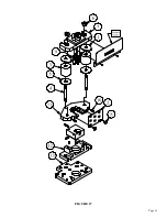
3.
Check the alignment of the unit. After cleaning the unit, always check the alignment of the punch
and die section. To check the alignment, insert the punch and holder, without the springs, into the
housing and check the gap. Make sure the punch is centered in the die. SEE FIGURE 23 BELOW.
4.
If proven correct, tighten the two M-10 socket head screws holding the die section in place.
5.
Apply some high pressure lube all around the inside of the housing, then re-assemble the unit,
reversing the above procedures.
CAUTION: WHEN USING THIS TOOL, ALWAYS WEAR SAFETY GLASSES.
Before operation, lubricate the sides and back of the upper die with way oil. Repeat this lubrication once
daily. Cutting blades should be lubricated, with a cutting oil or motor oil, before making the first cut and
after every 10 to 15 cuts.
Summary of Contents for 9012-24M
Page 10: ...Page 9 FIGURE 1 ...
Page 12: ...Page 11 FIGURE 2 ...
Page 16: ...Page 15 FIGURE 4A ...
Page 17: ...Page 16 FIGURE 4B ...
Page 18: ...Page 17 FIGURE 4C ...
Page 22: ...Page 21 FIGURE 6 ...
Page 24: ...Page 23 FIGURE 7 ...
Page 35: ...Page 34 THIS PAGE LEFT BLANK INTENTIONALLY ...
Page 40: ...Page 39 FIGURE 15 ...
Page 42: ...Page 41 FIGURE 16 ...
Page 48: ...Page 47 FIGURE 20 ...
Page 54: ...Page 53 FIGURE 24 ...
Page 56: ...Page 55 FIGURE 25 ...
Page 62: ...Page 61 FIGURE 27 ...
Page 66: ...Page 65 FIGURE 29 ...
Page 68: ...Page 67 FIGURE 30 ...
Page 74: ...Page 73 FIGURE 32 ...
Page 78: ...Page 77 FIGURE 34 ...
Page 80: ...Page 79 FIGURE 35 ...
Page 82: ...Page 81 FIGURE 36 ...
Page 84: ...Page 83 FIGURE 37 ...
Page 86: ...Page 85 FIGURE 38 ...
Page 90: ...Page 89 FIGURE 41 ...
Page 92: ...Page 91 FIGURE 42 ...
Page 93: ...Page 92 FIGURE 43 ...
Page 96: ...Page 95 THIS PAGE LEFT BLANK INTENTIONALLY ...
Page 98: ...Page 97 FIGURE 46 ...
Page 100: ...Page 99 FIGURE 47 ...