Page 48
The Channel Shear is a component tool designed to shear 2 to 6 inch (51 to 152mm) standard channel on
this model.
7.7 CHANNEL SHEAR
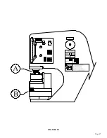
SEE FIGURE 21 ON THE FOLLOWING PAGE.
The Channel Shear installs under the upper arm in the tool station. The selector switch must be in the
SHEAR position to operate this tool. Before installing the tool, remove the upper blade. Install the
spring guide pins with the head down in the side plate of the shear. REFER TO THE INSERT IN
FIGURE 21. Slide the return springs over the guide pins, the short one first, followed by the long one.
Replace the top blade. Mount the shear as close to the frame as possible, with the locking handle to the
cylinder end. Make sure that the slug slot in the tool aligns with the slug slot in the tool table. Anchor
the tool with the finger clamps provided.
7.7A CHANNEL SHEAR INSTALLATION
The Channel Shear will shear from 2 to 6 inch (51 to 152mm) light weight channel with minimum
distortion. Lubricate the blades before the first cut and every 10 to 15 cuts, thereafter. Grease the
pressure block between the tool and the upper arm every two hours of operation.
The following are basic steps in shearing with the Channel Shear:
—
ADJUST BOTH THE MOVING AND STATIONARY SIDE BLADES TO THE SIZE OF
CHANNEL BEING SHEARED.
Improper adjustment of the vertical blades will result in damage to the channel shear. It is necessary to
reset the stationary side blades for each size of channel, to keep the channel centered in the unit.
ONE METHOD OF ACCOMPLISHING THIS ADJUSTMENT IS AS FOLLOWS:
Place a piece of channel, the size to be sheared, in the tool. Remove the lifting springs and lower the
upper blade by hand until it contacts the channel iron. Locate the channel so that the upper blade
contacts both legs, which will center it in the shear. Adjust the movable vertical blades up to the flange of
the channel. Loosen the fixed vertical blade clamps (four places) and slide the fixed blades up to the
channel flange. Tighten the blade clamps and adjust the back-up socket set screws up against the fixed
vertical blades. Now, check to see that the blades have good alignment, front and back, and have
maintained their perpendicular position to the lower blades.
—
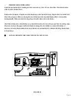
POSITION THE ADJUSTING HANDLE.
The adjusting handle can be relocated to permit easy opening and closing of the movable vertical blades.
(Approximately 1/2 turn will lock and unlock the workpiece.)
—
SET THE BOTTOM OF THE STROKE AS LOW AS POSSIBLE.
The bottom of the stroke should be set as low as possible, without bottoming any part of the upper blade,
blade holder or pressure block. The upper stroke should be set to allow the workpiece to feed freely
through the shear.
7.7B CHANNEL SHEAR OPERATION
Summary of Contents for 9012-24M
Page 10: ...Page 9 FIGURE 1 ...
Page 12: ...Page 11 FIGURE 2 ...
Page 16: ...Page 15 FIGURE 4A ...
Page 17: ...Page 16 FIGURE 4B ...
Page 18: ...Page 17 FIGURE 4C ...
Page 22: ...Page 21 FIGURE 6 ...
Page 24: ...Page 23 FIGURE 7 ...
Page 35: ...Page 34 THIS PAGE LEFT BLANK INTENTIONALLY ...
Page 40: ...Page 39 FIGURE 15 ...
Page 42: ...Page 41 FIGURE 16 ...
Page 48: ...Page 47 FIGURE 20 ...
Page 54: ...Page 53 FIGURE 24 ...
Page 56: ...Page 55 FIGURE 25 ...
Page 62: ...Page 61 FIGURE 27 ...
Page 66: ...Page 65 FIGURE 29 ...
Page 68: ...Page 67 FIGURE 30 ...
Page 74: ...Page 73 FIGURE 32 ...
Page 78: ...Page 77 FIGURE 34 ...
Page 80: ...Page 79 FIGURE 35 ...
Page 82: ...Page 81 FIGURE 36 ...
Page 84: ...Page 83 FIGURE 37 ...
Page 86: ...Page 85 FIGURE 38 ...
Page 90: ...Page 89 FIGURE 41 ...
Page 92: ...Page 91 FIGURE 42 ...
Page 93: ...Page 92 FIGURE 43 ...
Page 96: ...Page 95 THIS PAGE LEFT BLANK INTENTIONALLY ...
Page 98: ...Page 97 FIGURE 46 ...
Page 100: ...Page 99 FIGURE 47 ...

