


Page 40
7.3 6 X 6 NINETY DEGREE NOTCHER
The 6 x 6 ninety degree notcher is a component tool designed to cut 90 degree Vee notches in angle and
flat stock. It has a maximum capacity of 5/16 inch (8mm) thick mild steel.
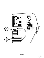
7.3A 6 X 6 NINETY DEGREE NOTCHER INSTALLATION
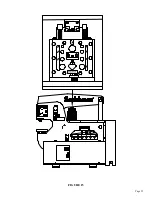
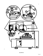
SEE FIGURE 16 ON THE FOLLOWING PAGE.
The 6 x 6 ninety degree notcher can be mounted either under the upper arm on the tool table or in the
punch station. When the notcher is mounted on the tool table, the selector switch must be in the SHEAR
position. When the notcher is in the punch station, the selector switch must be in the PUNCH position.
CAUTION: IN EITHER STATION, CARE MUST BE TAKEN TO SET THE UPPER AND
LOWER STROKE CONTROLS ON THE MACHINE. FAILURE TO DO SO WILL RESULT
IN DAMAGE TO THE TOOL AND POSSIBLE INJURY TO THE OPERATOR.
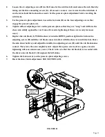
The upper stroke should be set so that the pusher assembly is held in place by the spring tension of the
tool. The lower stroke must be set so that the upper blade just passes the lower blades at the point of the
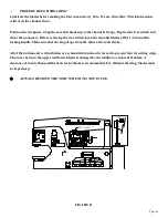
vee by no more than 1/16 of an inch (1.5mm). To install the notcher under the upper arm, the tool should
be mounted as close to the frame as possible and anchored with the bolts and thick washers (A) provided.
The pusher (B) and beam block (C) should be installed according to the dimensions IN FIGURE 16. To
mount the notcher in the punch station, first remove the die holder, stripper and punch. Mount the short
punch pusher (G) with the standard jam nut. Mount the notcher to the punch table with the front of the
notcher and the front of the punch table even. SEE FIGURE 16. Mount the notcher to the punch table,
using the bolts and washers (D) provided with the punch station. The punch pusher (G) and the notcher
pusher (E) should align as shown, with the punch pusher toward the front of the notcher pusher. The
tool may be slightly depressed to install under the ram.
7.3B 6 X 6 NINETY DEGREE NOTCHER OPERATION
Lubricate the blades before starting and every 10 to 15 cuts, thereafter. Lubricate the pusher bars
(B & C) every two hours of operation. Do not attempt to shear material thicker than 5/16 of an inch
(8mm) and never side-load the notcher. The slug must be removed with a magnetic probe or tongs after
every cut.
DO NOT REMOVE THE SLUGS BY HAND.
ALWAYS REMOVE THE NOTCHER WHEN IT IS NOT IN USE.
Summary of Contents for 9012-24M
Page 10: ...Page 9 FIGURE 1 ...
Page 12: ...Page 11 FIGURE 2 ...
Page 16: ...Page 15 FIGURE 4A ...
Page 17: ...Page 16 FIGURE 4B ...
Page 18: ...Page 17 FIGURE 4C ...
Page 22: ...Page 21 FIGURE 6 ...
Page 24: ...Page 23 FIGURE 7 ...
Page 35: ...Page 34 THIS PAGE LEFT BLANK INTENTIONALLY ...
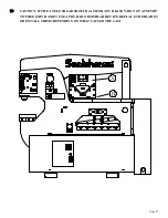
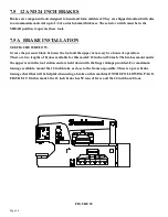
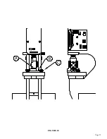
Page 40: ...Page 39 FIGURE 15 ...
Page 42: ...Page 41 FIGURE 16 ...
Page 48: ...Page 47 FIGURE 20 ...
Page 54: ...Page 53 FIGURE 24 ...
Page 56: ...Page 55 FIGURE 25 ...
Page 62: ...Page 61 FIGURE 27 ...
Page 66: ...Page 65 FIGURE 29 ...
Page 68: ...Page 67 FIGURE 30 ...
Page 74: ...Page 73 FIGURE 32 ...
Page 78: ...Page 77 FIGURE 34 ...
Page 80: ...Page 79 FIGURE 35 ...
Page 82: ...Page 81 FIGURE 36 ...
Page 84: ...Page 83 FIGURE 37 ...
Page 86: ...Page 85 FIGURE 38 ...
Page 90: ...Page 89 FIGURE 41 ...
Page 92: ...Page 91 FIGURE 42 ...
Page 93: ...Page 92 FIGURE 43 ...
Page 96: ...Page 95 THIS PAGE LEFT BLANK INTENTIONALLY ...
Page 98: ...Page 97 FIGURE 46 ...
Page 100: ...Page 99 FIGURE 47 ...