INSTALLATION
2.2
SUPERSET 23/23E/PLUS
ad-i2.pm5 P2
scm
2-1 MACHINE UNLOADING
Before unloading the machine, free it of all parts which, for transport or packing reasons are resting on it.
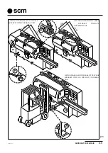
Check the red lifting bar (B fig. 2.1) is properly fastened to the machine bed.
Raise the machine using a crane or other means after fastening the cables supplied with hooks to the points
provided (C fig. 2.1) and indicated by means of plates.
NOTE: Always keep to the cable lengths shown in fig. 2.1; if necessary use longer cables. For machines without
universal units, always make sure there is a 150 mm difference between one cable and another.
During lifting, avoid sudden, jerky movements.
Alternatively to the above indications, the machine (when fitted with pedestal or pallet) can also be lifted by fork
lift truck having suitable length forks positioned at a distance indicated on plates (A fig. 2.1). The forks must be
inserted under the machine bed (fig. 2.1). Make sure the forks fit under the rear beam (D fig. 2.1). Take every
precaution to avoid any chance of the machine overturning, fastening it with cables to the fork lift truck structure.
Make sure that cranes, cables or fork lift trucks have a lifting capacity equal to or greater than the weight
of the machine.
Machine weight is indicated on the identity plate or in the “characteristics paragraph” of this manual.
2-2 POSITIONING
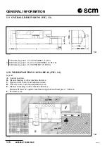
Choose the best, well-lit position (recommended minimum 500 LUX), taking into consideration power
connections to mains, to the compressed air system and to the shavings suction system, as well as easy
maintenance access. The minimum free distance around the machine should be 1000 mm, except in the operator
start-up and adjustments area where the distance must be 1500 mm and in the outfeed operator position, where
the distance must be equal to the maximum length of the machined piece plus 500 mm.
Check the floor is sound (non-deformable material is best, with concrete floor recommended), so the machine
bed rests uniformly on all contact points.
For machine transport requirements, a red bar (B fig. 2.1) is fitted. Once the machine has been positioned, remove
the bar (B). This bar (B) must be refitted every time the machine has to be moved.
For transport requirements, the machine is greased and oiled.
Before starting operation, remove grease from work areas and protection devices.
The machine bed is equipped with special feet inside which screws can be fitted for levelling the machine.
2-3 LEVELLING
Position the machine as required. Place a high-precision spirit level (0.05 mm per metre) above the table in line
with each spindle, first lengthways and then crossways, making all preliminary adjustments by means of the
screws (12x25 m hexagonal-head in the accessory pack) under the feet. Between the screws and the floor,
position the bosses provided in the accessory pack (P fig. 2.1)
Adjust the screws again and at the same time check the variations produced. A maximum levelness error of 0.1
mm is acceptable along the entire length of the worktables.
To level crossways, place the spirit level near the first spindle and move it 300 mm at a time.
The infeed table must be perfectly aligned to the fixed machine worktable. Any maladjustment between the two
tables should not exceed 0.1 mm lengthways and 0.05 mm crossways.
Summary of Contents for Superset 23
Page 2: ...VUOTO AI ...
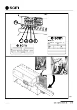
Page 25: ...SUPERSET 23 23E PLUS 2 5 ad i2 pm5 P5 scm 2 2 PE L2 L3 L1 N COM2 3 125 007 Ec 0 G G ...
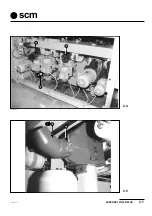
Page 27: ...SUPERSET 23 23E PLUS 2 7 ad i2 pm5 P7 scm 2 5 N L 125 012 Ez 0 U U 2 4 N ...
Page 32: ...INSTALLATION 2 12 SUPERSET 23 23E PLUS ad i2 pm5 P12 scm ...
Page 45: ...HEADS SUPERSET 23 23E PLUS 4 3 ad i4_1 P3 scm D L C M 4 1 A 4 1a 4 1b max 1 5mm min 22mm T Z ...
Page 51: ...HEADS SUPERSET 23 23E PLUS 4 9 ad i4_2 P9 scm 4 5 4 4 A D C B S SUP310 SUP311_L V ...
Page 57: ...HEADS SUPERSET 23 23E PLUS 4 15 ad i4_2 P15 scm 4 10 3 18 D 7 5 4 6 ...
Page 61: ...HEADS SUPERSET 23 23E PLUS 4 19 ad i4_3 P19 scm 4 13 4 14 L H G H SUP325_L SUP326_L I A S D M ...
Page 65: ...HEADS SUPERSET 23 23E PLUS 4 23 ad i4_3 P23 scm SUP353_L A 4 17 ...
Page 67: ...HEADS SUPERSET 23 23E PLUS 4 25 ad i4_3 P25 scm SUP312_L F G 4 20 SUP342_L Y I X K L N 4 19 ...
Page 71: ...HEADS SUPERSET 23 23E PLUS 4 29 ad i4_3 P29 scm 4 24 G U V I ...
Page 73: ...HEADS SUPERSET 23 23E PLUS 4 31 ad i4_3 P31 scm 4 26 4 27 F M T G B ...
Page 76: ...HEADS 4 34 SUPERSET 23 23E PLUS ad i4_3 P34 scm ...
Page 79: ...OPTIONAL UNITS SUPERSET 23 23E PLUS 10 3 ad i10_1 P3 scm 10 4 B C A SUP359_L 10 3 K SUP347 ...
Page 85: ...OPTIONAL UNITS SUPERSET 23 23E PLUS 10 9 ad i10_1 P9 scm SUP3331_L 10 10 E D X ...
Page 93: ...OPTIONAL UNITS SUPERSET 23 23E PLUS 10 17 ad i10_1 P17 scm 10 20 10 21 SUP321 SUP3 20 V L P ...
Page 95: ...OPTIONAL UNITS SUPERSET 23 23E PLUS 10 19 ad i10_2 P19 scm 10 22 E C D A B SUP327_L ...
Page 97: ...OPTIONAL UNITS SUPERSET 23 23E PLUS 10 21 ad i10_2 P21 scm 10 23 L N M G F H SUP328_L ...
Page 99: ...OPTIONAL UNITS SUPERSET 23 23E PLUS 10 23 ad i10_2 P23 scm 10 25 sup327_l T S E F D ...
Page 101: ...OPTIONAL UNITS SUPERSET 23 23E PLUS 10 25 ad i10_2 P25 scm 10 26 SUP331_L Y W X Z R U V ...
Page 103: ...OPTIONAL UNITS SUPERSET 23 23E PLUS 10 27 ad i10_2 P27 scm 10 28 M N G F U ...
Page 107: ...OPTIONAL UNITS SUPERSET 23 23E PLUS 10 31 ad i10_2 P31 scm 10 32 R A U H F W C D B K E ...
Page 108: ...OPTIONAL UNITS 10 32 SUPERSET 23 23E PLUS ad i10_2 P32 scm ...
Page 109: ...SUPERSET 23 23E PLUS 19 1 19 SECTION 19 SELF BRAKING MOTOR ...
Page 111: ...SUPERSET 23 23E PLUS 19 3 19 19 1 19 2 freno1 freno2 ...
Page 112: ...SELF BRAKING MOTOR 19 4 SUPERSET 23 23E PLUS SEZ I19 ...
Page 115: ...MAINTENANCE SUPERSET 23 23E PLUS 20 3 ad i20_1 P3 scm 20 3 7 1 3 2 4 5 G 6 20 2 20 1 ...
Page 129: ...MAINTENANCE SUPERSET 23 23E PLUS 20 17 ad i20_2 pm5 P17 scm 20 20 S U P 4 2 2 _ M A ...
Page 136: ...APPENDIX A 2 SUPERSET 23 23E PLUS ad appen pm5 P2 scm ...
Page 137: ...SUPERSET 23 23E PLUS A 3 ad appen pm5 P3 scm APPENDIX ...
Page 138: ...APPENDIX A 4 SUPERSET 23 23E PLUS ad appen pm5 P4 scm ...
Page 139: ...SUPERSET 23 23E PLUS A 5 ad appen pm5 P5 scm APPENDIX ...
Page 140: ...APPENDIX A 6 SUPERSET 23 23E PLUS ad appen pm5 P6 scm ...
Page 141: ...SUPERSET 23 23E PLUS A 7 ad appen pm5 P7 scm APPENDIX ...
Page 142: ...APPENDIX A 8 SUPERSET 23 23E PLUS ad appen pm5 P8 scm ...
Page 143: ...SUPERSET 23 23E PLUS A 9 ad appen pm5 P9 scm APPENDIX ...
Page 144: ...APPENDIX A 10 SUPERSET 23 23E PLUS ad appen pm5 P10 scm ...
Page 145: ...SUPERSET 23 23E PLUS A 11 ad appen pm5 P11 scm APPENDIX ...

