Maintenance and Care
26
01.02|SPG 100|en
Disassembly of the gripper
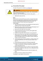
Position of the position numbers
WARNING
Risk of injury when the machine/system moves unexpectedly!
Remove the energy supplies.
Make sure that no residual energy remains in the system.
1 Remove the pressure lines.
NOTE
Even after the removal of the pressure lines, the piston chamber
that was last subjected to compressed air will still be under pres-
sure due to the integrated pressure maintenance valve. This
pressure chamber must be bled before the gripper is
disassembled.
2 Open the locking screws (47) in the lid (9) and in the base jaw (2),
until the pressure chamber has been bled.
3 Remove the snap ring (51) and pull the pinion bearing (11) out
of the housing using a screw or an extractor.
4 Remove the pinion (8) from the housing.
5 Pull the cylindrical pins (40) out of the covering plate (10)
using a screw or an extractor.
6 Undo the screws (34) and remove the covering plate (10).
7 Remove both of the snap rings (50) and pull the lid (9) out of
the base jaws (2). If the lid jams, remove the snap ring (52)
and the locking screw (47). The lid (9) can then be pulled out
using a screw or an extractor.
8 Push the base jaws (2) into the position „Gripper closed” and
unscrew the piston (6) out of the base jaws (2) with a face
wrench.
9 Then pull the base jaws (2) out of the guide beads (3).
10 Pull the cylindrical pins (40) out of the piston rod (5) using a
screw or an extractor, remove the screws (32) and then
remove the piston rod (5).
11 Remove both locking screws (17) and the O-rings (24) and press
the pressure maintenance valve (16), or the sealing bolt (12) out
of the piston rod (5).
12 Clean all parts thoroughly and check all parts for defects and
wear.
13 Replace all seals according to the seal kit list.
The gripper is assembled in reverse order.
9.4
www.comoso.com


