Technical data
20
01.00|ROTA THW vario |en-US
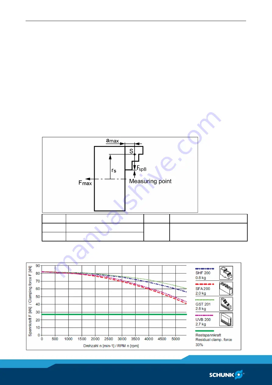
Clamping force RPM diagrams
The diagrams relate to a 3-jaw chuck.
Clamping force/RPM curves have been determined by using hard
jaws. In the determination process, the maximum actuating force
was applied and the jaws were set flush with the outer diameter of
the chuck.
The chuck is in perfect condition and lubricated with SCHUNK
LINOMAX special grease.
If one or more of these prerequisites is modified, the graphs will
no longer be valid.
Chuck setup for clamping force/RPM diagram
F
spB
Jaw clamping force
S
Center of gravity
r
s
Center of gravity radius
a
max
Max. jaw eccentricity of center
of gravity in axial direction
F
max
Max. actuating force
Clamping force RPM diagram for ROTA THW
6.2
Summary of Contents for ROTA THWvario
Page 60: ...Assembly drawing 60 01 00 ROTA THW vario en US Assembly drawing ROTA THW vario 215 62 13 13 1 ...
Page 61: ...Assembly drawing 01 00 ROTA THW vario en US 61 ...
Page 62: ...Assembly drawing 62 01 00 ROTA THW vario en US Segmented mandrel ROTA THW vario D 13 1 1 ...
Page 63: ...Assembly drawing 01 00 ROTA THW vario en US 63 Collet chuck ROTA THW vario F 13 1 2 ...


