


Technical data
01.00|ROTA THW vario |en-US
21
Calculating the clamping force and RPM
Missing information or specifications can be requested from the
manufacturer.
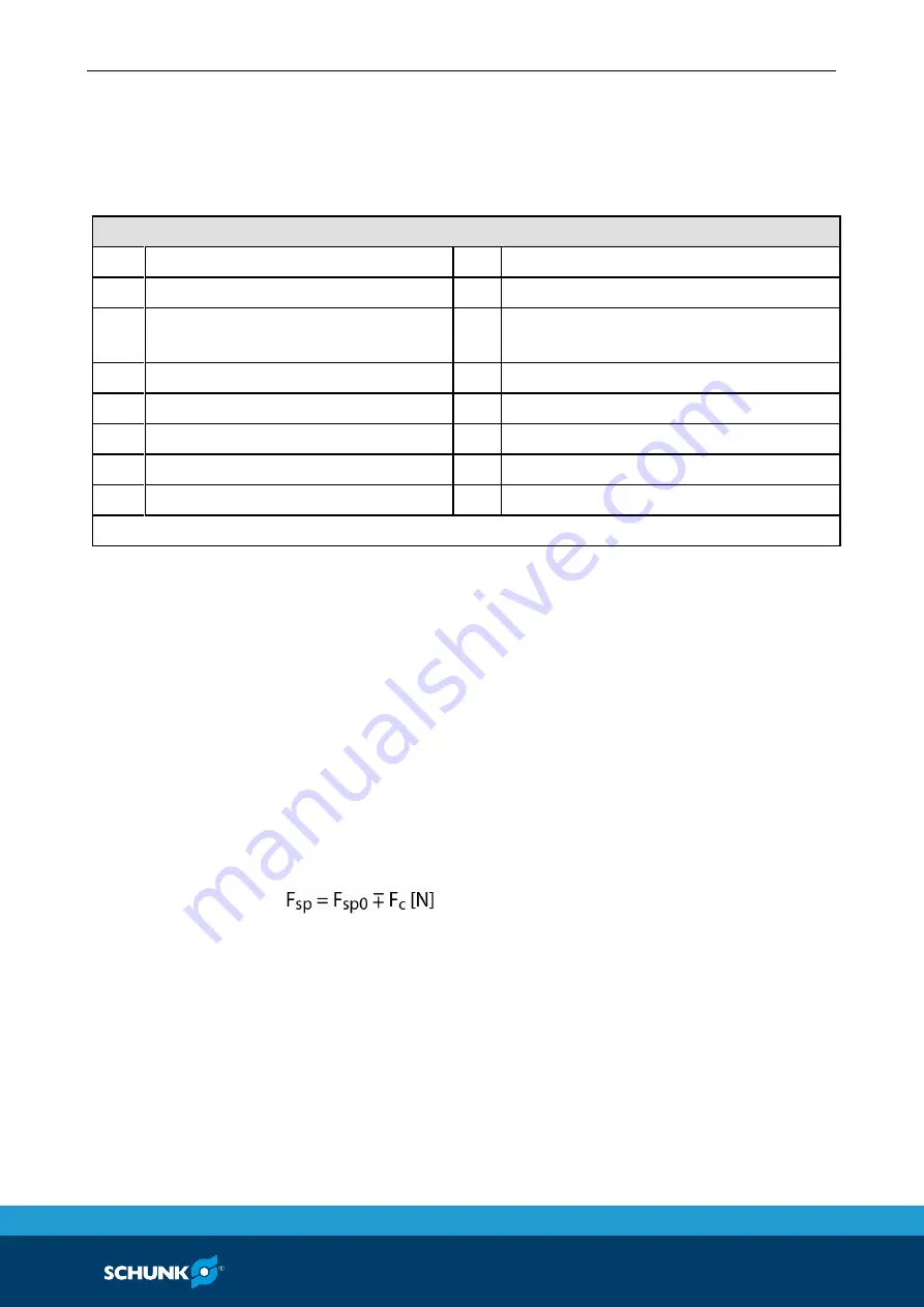
Legend
F
c
Total centrifugal force [N]
M
cAB
Centrifugal torque of top jaws [kgm]
F
sp
Effective clamping force [N]
M
cGB
Centrifugal torque of base jaws [kgm]
F
spmin
minimum required clamping force
[N]
n
Speed of rotation [RPM]
F
sp0
Initial clamping force [N]
r
s
Center of gravity radius [mm]
F
spz
Cutting force [N]
r
sAB
Center of gravity radius of top jaw [mm]
m
AB
Mass of one top jaw [kg]
s
sp
Safety factor for clamping force
m
B
Mass of chuck jaw set [kg]
s
z
Safety factor for machining
M
c
Centrifugal torque [kgm]
Σ
s
Max. clamping force of lathe chuck [N]
kgm × 9.81 = Nm
Calculation of the required clamping force at a specified speed of
rotation
The initial clamping force F
sp0
is the total force impacting radially
on the workpiece via the jaws due to actuation of the lathe chuck
during shutdown. Under the influence of rotation, the jaw mass
generates an additional centrifugal force. The centrifugal force
reduces or increases the initial clamping force depending on
whether gripping is from the outside inwards or from the inside
outwards.
The sum of the initial clamping force
F
sp0
and the
total centrifugal
force F
c
is
the effective clamping force F
sp
.
(–)
for gripping from the outside inwards
(+)
for gripping from the inside outwards
6.3
6.3.1
Summary of Contents for ROTA THWvario
Page 60: ...Assembly drawing 60 01 00 ROTA THW vario en US Assembly drawing ROTA THW vario 215 62 13 13 1 ...
Page 61: ...Assembly drawing 01 00 ROTA THW vario en US 61 ...
Page 62: ...Assembly drawing 62 01 00 ROTA THW vario en US Segmented mandrel ROTA THW vario D 13 1 1 ...
Page 63: ...Assembly drawing 01 00 ROTA THW vario en US 63 Collet chuck ROTA THW vario F 13 1 2 ...