


Technical data
01.00|ROTA THW vario |en-US
23
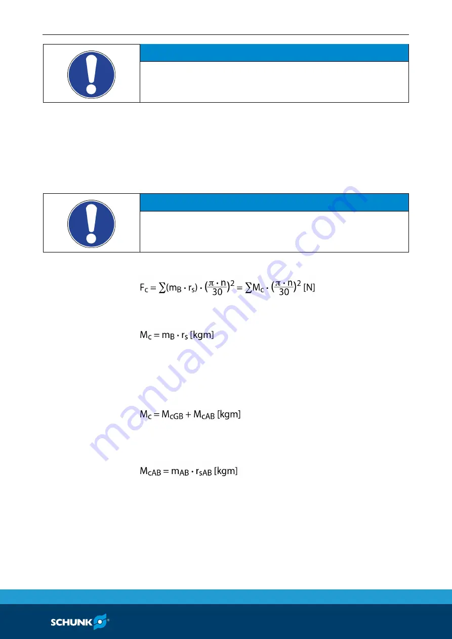
NOTICE
This calculated force must not be larger than the maximum
clamping force
Σ
S engraved on the lathe chuck.
See also "Lathe chuck data" table Link Futterdaten
From the above formula it is evident that the sum of the effective
clamping force F
sp
and the total centrifugal force F
c
is multiplied by
the
safety factor for the clamping force S
sp
. According to VDI
3106, the following also applies here:
S
sp
≥ 1.5.
The
total centrifugal force F
c
is dependent on both the sum of the
masses of all jaws and on the center of gravity radius and the rpm.
NOTICE
For safety reasons, in accordance with DIN EN 1550, the
centrifugal force may be a maximum of 67% of the initial
clamping force.
The formula for the calculation of the total centrifugal force F
c
is:
For this,
n is the given speed of rotation
in RPM. The product
m
B
∙
r
s
is referred to as the centrifugal torque M
c
.
In case of toolholders with split chuck jaws, i.e., with base jaws and
top jaws, for which the base jaws change their radial position only
by the stroke amount, the
centrifugal torque of the base jaws
M
cGB
and the
centrifugal torque of the top jaws M
cAB
need to be
added:
The centrifugal torque of the base jaws M
cGB
can be found in the
table "Lathe chuck data"Link Futterdaten. The centrifugal torque
of the top jaws M
cAB
is calculated as per:
Calculation example: required initial clamping force for a given
RPM
Required initial clamping force F
sp0
for a given RPM n
The following data is known for the machining job:
• Gripping from the outside in (application-specific)
• Machining force F
spz
= 3000 N (application-specific)
6.3.2
Summary of Contents for ROTA THWvario
Page 60: ...Assembly drawing 60 01 00 ROTA THW vario en US Assembly drawing ROTA THW vario 215 62 13 13 1 ...
Page 61: ...Assembly drawing 01 00 ROTA THW vario en US 61 ...
Page 62: ...Assembly drawing 62 01 00 ROTA THW vario en US Segmented mandrel ROTA THW vario D 13 1 1 ...
Page 63: ...Assembly drawing 01 00 ROTA THW vario en US 63 Collet chuck ROTA THW vario F 13 1 2 ...