Attachment of the entire manual chuck
7 Attachment of the entire manual chuck
The item numbers specified for the corresponding individual
components relate to chapter drawings.
7.1 Handling prior to attachment
See the
ROTA-S plus
or
ROTA-S plus 2.0
Assembly and Operating
Manual contained in the scope of delivery.
7.2 Preparing the chuck attachment
• Check the machine table and ready-machined intermediate
flange for radial and axial runout. The permissible limit is 0.005
mm as per DIN 6386 and ISO 3089.
• The contact surface must be chamfered and clean. Rectify any
damage of the machine table contact surfaces.
7.3 Assembly of the entire manual chuck
Insert the T-nuts (item 15) into the grooves provided in the
machine table. Then lift the toolholder and supplied eye bolts onto
the machine table. Align centrally with the centering pins (item 8)
and radially with the location bolts (item 21) on the manual lathe
chuck. Then fasten the chuck according to the specified torque
using a torque wrench with the screws (item 14) and the T-nuts.
To protect the counterbore holes against contamination, fit the
caps (items 9, 10).
The radial and axial run-out accuracy to be reached depend on the
diameter of the chuck.
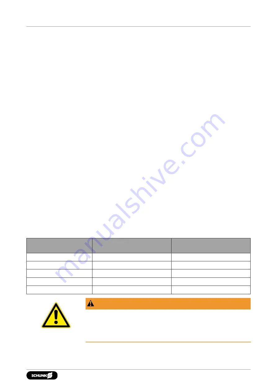
The following table shows the attainable maximum radial and axial
run-out tolerances.
Chuck size [mm]
Max. radial run-out tolerance
[mm]
Max. axial run-out tolerance
[mm]
550
0.02
0.03
700
0.03
0.04
1000
0.03
0.05
1200
0.03
0.05
1400
0.03
0.06
WARNING
Risk of injury from mounting screw brass caps (items 9 and 10)
being flung out when chuck turns.
The mounting screw brass caps (items 9 and 10) must only be
applied for stationary use of the chuck.
27
06.00 | ROTA-S flex | Assembly and Operating Manual | en | 0889139


