


8
Montage- und Betriebsanleitung für Schwenkkopf
Type PSK 45, PSK 57-N/1, PSK 57-N/2
Assembly and Operating Manual for Swivel Head
Type PSK 45, PSK 57-N/1, PSK 57-N/2
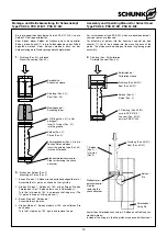
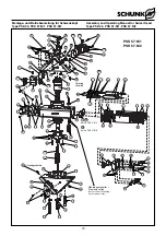
10.1 Zerlegen der Schwenkeinheit
(Pos.-Nr. siehe Kapitel 12. Explosionszeichnung)
HINWEIS:
Beim Schwenkkopf PSK 57-N müssen die Kolbendichtungen
(Pos. 40 und 41) mit Hilfe einer Vorrichtung montiert werden.
Zusätzlich ist beim PSK 57-N/2 eine Vorrichtung zum Montieren
der Kolben notwendig. Zeichnungen zum Bau der Vorrichtungen
sowie zur Montage sind ab Seite 10 abgebildet.
1. Entfernen Sie die Druckleitungen.
2. Demontieren Sie die Näherungsschalter.
3. Klemmen Sie die Elektrokabel ab.
4. Entfernen Sie die PG Verschraubung (Pos. 39).
5. Entfernen Sie die Schrauben (Pos. 69) mit Unterlegscheiben
(Pos. 71 - je 2 Stück) und nehmen Sie den Anschraubwinkel
(Pos. 19) ab.
6. Schrauben Sie die Verteilerkästen (Pos. 27) durch Lösen der
Schrauben (Pos. 83) ab.
7. Ziehen Sie die Deckel (Pos. 25) aus den Verteilerkästen, ver-
wenden Sie hierfür die Abzugsgewinde M 4, nachdem Sie
die Verschlussgewindestifte (Pos. 89) entfernt haben.
8. Klemmen Sie die Kabel ab, und ziehen Sie sie zunächst aus
den Verteilerkästen und anschließend in Richtung Verteiler-
flansch (Pos. 17) aus dem Schwenkkopf.
HINWEIS:
Der Schwenkkörper (Pos. 21) braucht nur dann vom Ritzel
(Pos. 15) getrennt werden falls eines der beiden Teile defekt ist,
oder wenn Sie die O-Ringe (Pos. 52) zwischen Ritzel und
Schwenkkörper prüfen oder ersetzen wollen. Anderenfalls weiter
bei Punkt 11.
9. Entfernen Sie den Deckel (Pos. 18) durch demontieren der
Schrauben (Pos. 66).
10. Lösen Sie die Schrauben (Pos. 70) sowie die Paßschrauben
(Pos. 76 - je 2 Stück) und schrauben Sie damit den
Schwenkkopf (Pos. 21) ab.
11. Markieren Sie die Einbaulage des Verteilerflansches
(Pos. 17) und demontieren Sie diesen durch Entfernen der
Schrauben (Pos. 68).
12. Schrauben Sie die Deckel (Pos. 3 bzw. 37) sowie (Pos. 4)
durch Entfernen der Schrauben (Pos. 59, 61, 62, 67) ab.
13. Markieren Sie die Einbaulage der Kolben (Pos. 2) und des
Ritzels (Pos. 14), um den Zusammenbau zu erleichtern.
14. Entfernen Sie den Sicherungsring (Pos. 85).
15. Drücken Sie das Ritzel (Pos. 15) aus dem Gehäuse, (gege-
benenfalls zusammen mit dem Schwenkkörper Pos. 21).
16. Schieben Sie die Kolben (Pos. 2) aus dem Gehäuse.
17. Demontieren Sie die Stoßdämpfer (siehe Aus- und Einbau
eines Stoßdämpfers, Kapitel 10.2).
18. Entfernen Sie alle Dichtungen gemäß Dichtsatzliste.
19. Reinigen Sie alle Teile und kontrollieren Sie alle Teile auf
Defekt und Verschleiß.
20. Alle Dichtungen laut Dichtsatzliste erneuern (Kapitel 13.1).
Der Zusammenbau erfolgt in umgekehrter Reihenfolge.
Beachten Sie dabei die Hinweise am Anfang dieses Kapitels und
die Kapitel 10.2 und 10.3.
ACHTUNG!
Beschädigen Sie beim Zusammenbau keine Kabel
und Dichtungen!
Für die Montage der Kolben und Dichtungen sind
beim Schwenkkopf PSK 57- N Montagevorrichtungen
erforderlich (siehe Kapitel 10.3 und 11).
10.1 Disassembly of the swivel head
(For Pos.-No. see chapter 12. Drawings)
NOTE:
For PSK 57-N the piston seals (Pos. 40 and 41) have to be moun-
ted by means of a mounting device.
For PSK 57-N/2 an addional mounting device for mounting the
pistons is necessary. For drawings of how to build such a device,
as well as a mounting instruction, see page 10 and following.
1. Remove all pressure lines.
2. Detach the proximity switches.
3. Remove the electric cables.
4. Remove the PG screwed connection (Pos. 39).
5. Remove the screws (Pos. 69) and the washers (Pos. 71 - two
each pieces) and take off the angular backplate (Pos. 19).
6. Unscrew the distributing box (Pos. 27) by loosening the
screws (Pos. 83).
7. Draw out the covers (Pos. 25) from the distributing boxes.
Herefore, please use the provided thread M 4, after having
removed the sealing set screws (Pos. 89).
8. Remove the cable and draw them out of the distributing box
and then out of the swivel head in direction of the distributing
flange (Pos. 17).
NOTE:
The swivelling body (Pos. 21) must only be separated from the
pinion (Pos. 15), if one of the two components are defective, or if
you want to inspect or replace the O-rings (Pos. 52) between the
pinion and the swivelling body. Otherwise, please continue with
point 11.
9. Remove the cover (Pos. 18) by removing the screws (Pos.
66).
10. Loosen the screws (Pos. 70) as well as the fitting screws
(Pos. 76 - 2 each pieces) and unscrew the swivel head (Pos.
68).
11. Mark the installation position of the distributing flange (Pos.
17) and disassemble it by removing the screws (Pos. 68).
12. Unscrew the covers (Pos. 3 or 37) as well as (Pos. 4) by
removing the screws (Pos. 59, 61, 62, 67).
13. Mark the installation position of the piston (Pos. 2) and of the
pinion (Pos. 14) – this will make the assembly easier.
14. Remove the safety ring (Pos. 85).
15. Push the pinion (Pos. 15) out of the housing, (if necessary,
together with the swivelling body Pos. 21).
16. Push the pistons (Pos. 2) out of the housing.
17. Disassemble the shock absorber (see assembly and dis-
assembly of shock absorbers, chapter 10.2).
18. Remove all seals as per seal kit list.
19. Thoroughly clean all components and control all components
on damage and wear out.
20. All exchange all seals as per seal kit list (chapter 13.1).
Assembly is done in reverse order.
Please consider the notes at the beginning of this chapter and the
chapters 10.2 and 10.3.
CAUTION!
Make sure that you that you won’t dammage a cable
or a seal during assembly!
For mounting of the pistons and seal at the swivel
head PSK 57-N assembly devices are necessary (see
chapter 10.3 and 11).


