SCHUNK PSK 45 Assembly And Operating Manual Download Page 6

6

Montage- und Betriebsanleitung für Schwenkkopf
Type PSK 45, PSK 57-N/1, PSK 57-N/2

Assembly and Operating Manual for Swivel Head
Type PSK 45, PSK 57-N/1, PSK 57-N/2

6.

Luftanschluss

ACHTUNG!

Beim Anschließen muss die Energieversorgung ab-
geschaltet sein. Beachten Sie auch die Sicherheits-
hinweise auf den Seiten 3 und 4.

Die Luftanschlüsse für die Schwenkbewegung sind mit Drossel-
rückschlagventilen ausgerüstet. Diese dienen zur Einstellung der
Drehgeschwindigkeit die am fertig montierten System eingestellt
werden muss.

Druckmittel:  Druckluft
Anforderung an die Güteklasse der Druckluft nach DIN 
ISO 8573-1: Güteklasse 4.

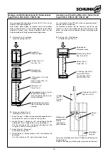
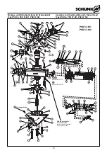
Interne Energiedurchführung:

(Pos.-Nr. siehe Kapitel 12. Explosionszeichnung)

Die Anschlüsse für die interne Energiedurchführung sind ge-
kennzeichnet (Nr. 1 – 8). Für den Direktanschluss werden 16 O-
Ringe (Pos. 51) mitgeliefert. Für PSK 45 in der Größe Ø 4 x 1,5
(empfohlene Senkung: Ø 7 x 1 tief) und für PSK 57-N Ø 6 x 2
(empfohlene Senkung: Ø 10 x 1,4 tief).
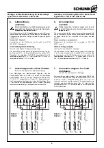
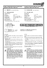
7.

Anschlussplan der 4-fach Verteiler

(Pos.-Nr. siehe Kapitel 12. Explosionszeichnung)

Zum Übertragen von elektronischen Signalen sind die
Schwenkköpfe PSK 45 und PSK 57-N jeweils mit 8 dreipoligen
Kupplungsdosen (Pos. 113) sowie 2 integrierten Kabeln (Pos.
110, Pos. 111) ausgestattet (je 1 Kabel für 4 Kupplungsdosen).
Die Kupplungsdosen befinden sich in den Verteilerkästen (Pos.
27) die seitlich am Schwenkkörper (Pos. 21) sitzen. Die Kabel
führen durch die Bohrung in der Lagerwelle aus dem PSK.

6.

Air connection

CAUTION!

During connection, the power supply must be swit-
ched off. Please observe the safety instructions on
pages 3 and 4.

The air connections for the swivel movement are equipped with
one-way restrictors. These are used for adjustment of the rotatio-
nal speed which has to be adjusted on the ready mounted
system.

Pressure medium: compressed air
Requirements to compressed air according to DIN ISO 
8573-1: class 4.

Internal energy supply:

(For Pos.-No. see chapter 12. Drawings)

The connections for the internal energy suply are marked (No. 
1 – 8). For direct connection 16 O-rings (Pos. 51) out of the little
plastic bag are used. For PSK 45 they have the size of Ø 4 x 1.5
(recommended countersunk: Ø 7 x 1 deep) and for PSK 57-N 
Ø 6 x 2 (recommended countersunk: Ø 10 x 1.4 deep).

7.

Connection diagram for 4-fold
distributors

(For Pos.-No. see chapter 12. Drawings)

For transmission of electric signals, the swivel heads PSK 45 and
PSK 57-N are equipped with 8 3-poles coupler sockets (Pos. 113)
as well as with 2 integrated cables (Pos. 110, Pos. 111) 
(one each cable for 4 coupler sockets). The coupler sockets are
situated inside the distributing boxes (Pos. 27), laterally at the
swivelling body (Pos. 21). The cables lead out of the bore of the
PSK into the pinion.

+

out

+

out

1

PNP

2

PNP

+

out

7

PNP

+

out

8

PNP

braun / brown

grau / grey

Last / Load 1

Last / Load 2

Last / Load 7

Last / Load 8

0V

0V

0V

0V

weiß / white

gelb / yellow

grün / green

rosa / pink

N 1

N 2

N 8

N 7

+ 24 V

0V

+

out

+

out

3

PNP

4

PNP

+

out

5

PNP

+

out

6

PNP

braun / brown

grau / grey

Last / Load 3

Last / Load 4

Last / Load 5

Last / Load 6

0V

0V

0V

0V

weiß / white

gelb / yellow

grün / green

rosa / pink

N 3

N 4

N 6

N 5

+ 24 V

0V

Kabel 1 /
Cable 1

Kabel 2 /
Cable 2

Summary of Contents for PSK 45

Page 1: ...SCHUNK Intec N V S A Tel 32 53 853504 Fax 32 53 836022 info be schunk com www be schunk com CANADA SCHUNK Intec Corp Tel 1 905 712 2200 Fax 1 905 712 2210 info ca schunk com www ca schunk com CHINA SC...

Page 2: ...necting diagram for 4 fold distributors 6 8 Schwenkwinkeleinstellung Adjusting the swivel angle 7 9 Problemanalyse Trouble shooting 7 10 Wartung und Pflege Maintenance and care 7 10 1 Zerlegen der Sch...

Page 3: ...modules protective covers must be used according to EC Machine Directive Point 1 4 1 Sicherheit 1 1 Symbolerkl rung Dieses Symbol ist berall dort zu finden wo besondere Gefahren f r Personen oder Bes...

Page 4: ...fahren durch herabfallende und herausgeschleuderte Gegenst nde Es m ssen Vorkehrungen getroffen werden um das Herabfallen oder das Herausschleudern von eventuell gef hrlichen Gegenst nden bearbeitete...

Page 5: ...18H7 und die Zentrierh lsen Pos 28 aus dem Beipack vor gesehen Verwenden Sie beim PSK 57 N zus tzlich die Unterlegscheiben Pos 53 3 Scope of delivery Swivel Head PSK 45 PSK 57 N 1 oder PSK 57 N 2 with...

Page 6: ...connection CAUTION During connection the power supply must be swit ched off Please observe the safety instructions on pages 3 and 4 The air connections for the swivel movement are equipped with one w...

Page 7: ...omplette Dichtsatz ist bei Schunk erh ltlich 4 Soweit nicht anderst vorgeschrieben sind alle Schrauben und Muttern mit einem Anzugsmoment gem DIN anzuziehen und mit Loctide Nr 243 oder Gleichwertigem...

Page 8: ...Anfang dieses Kapitels und die Kapitel 10 2 und 10 3 ACHTUNG Besch digen Sie beim Zusammenbau keine Kabel und Dichtungen F r die Montage der Kolben und Dichtungen sind beim Schwenkkopf PSK 57 N Montag...

Page 9: ...nd 93 4 Assembly is done in reverse order Assembly and Disassembly for PSK 57 N For Pos No see chapter 12 Drawings and illustration below 1 Remove the cover Pos 3 or 37 2 Remove the safety ring Pos 86...

Page 10: ...pin the 2nd piston may be used without seal Spreizh lse Expansion sleeve Dichtung Pos 40 Seal Pos 40 Montagekegel Assembly taper 2 O Ringe Pos 41 in Nut einlegenl Insert 2 O rings Pos 41 into the gro...

Page 11: ...1x45 Montagekegel Werkstoff Aluminium poliert Mounting taper Material polished aluminum Spreizh lse Werkstoff Delrin oder Nylon Expansion sleeve Material Delrin or Nylon Kalibrierh lse Werkstoff Alum...

Page 12: ...n 12 Drawings N herungsschalter Proximity switch auf besondere Bestellung upon separate order 66 10 49 1 36 85 45 46 88 37 3 23 30 46 42 80 97 81 4 5 72 56 81 59 62 11 88 17 68 68 54 20 28 65 20 22 71...

Page 13: ...er 66 10 49 1 36 85 45 46 81 37 3 23 30 40 72 62 62 81 4 5 40 42 59 59 59 80 97 81 41 56 11 88 68 53 68 17 54 20 65 28 20 22 71 39 75 19 69 84 71 69 87 51 88 49 86 66 81 61 61 67 35 50 15 83 27 52 88...

Page 14: ...11 032 O Ring O ring DIN 3771 NBR 82 27 x 1 78 1 46 9611 058 O Ring O ring DIN 3771 NBR 60 00 x 2 0 4 49 9611 081 O Ring O ring DIN 3771 NBR 6 00 x 1 5 4 50 9611 016 O Ring O ring DIN 3771 NBR 25 12 x...

Page 15: ...2 45 9611 032 O Ring O ring DIN 3771 NBR 82 27 x 1 78 1 46 9611 025 O Ring O ring DIN 3771 NBR 47 35 x 1 78 4 49 9611 063 O Ring O ring DIN 3771 NBR 6 00 x 1 0 4 50 9611 016 O Ring O ring DIN 3771 NB...

Page 16: ...Ring O ring DIN 3771 NBR 4 00 x 1 5 8 54 9611 519 O Ring O ring DIN 3771 NBR 11 00 x 2 0 8 56 9612 636 Dichtung Seal GM 2000 M 12 2 58 9938 995 O Ring O ring DIN 3771 NBR 122 00 x 2 0 1 59 9660 073 S...

Page 17: ...ng DIN 3771 NBR 25 12 x 1 78 9 52 9611 112 O Ring O ring DIN 3771 NBR 4 00 x 1 5 8 54 9611 519 O Ring O ring DIN 3771 NBR 11 00 x 2 0 8 56 9612 636 Dichtung Seal GM 2000 M 12 2 59 9660 073 Schrauben S...

Page 18: ...cable diameter Do not allow the sensor to make contact with a detectable object of a hard substance or to chemicals especially nitric acid chromic acid and sulfure acid The proximity switches used ar...

Page 19: ...Verstellung m ssen die Gewindestifte Pos 10 erneut mit einem geeigneten Klebstoff gesichert werden Mounting of proximity switches For Pos No see chapter 12 Assembly CAUTION For every assembly work the...

Reviews: