


5
Montage- und Betriebsanleitung für Schwenkkopf
Type PSK 45, PSK 57-N/1, PSK 57-N/2
Assembly and Operating Manual for Swivel Head
Type PSK 45, PSK 57-N/1, PSK 57-N/2
3.
Lieferumfang
– Schwenkkopf PSK 45, PSK 57-N/1 oder PSK 57-N/2
(ohne Adapterplatte und Näherungsschalter)
– Beipack: (siehe auch Kapitel 12.2)
6 Zentrierhülsen (zur Fixierung)
8 Zylinderschrauben (zur Befestigung von Anbauten)
4 Zylinderschrauben (zur Befestigung des Schwenkkopfes)
12 Unterlegscheiben (nur bei PSK 57-N zur Befestigung)
16 Gewindestifte (zum Verschluss nicht benötigterLuftanschl.)
16 O-Ringe (für schlauchlosen Direktanschluss)
2 O-Ringe 5 x 1,5 (zur Klemmung der Näherungsschalter)
ZUBEHÖR: (bei separater Bestellung, siehe Katalog)
– Näherungsschalter
– Adapterplatten
4.
Technische Daten
(siehe Katalog)
HINWEIS:
Bitte prüfen Sie, ob Ihr Einsatzfall anhand des Berechnungs-
programms »Auswahlsystem für SCHUNK-Schwenkeinheiten«
geprüft wurde. Falls nicht, kann keine Gewährleistung übernom-
men werden.
– Der vom Schwenkkopf ausgehende Luftschall ist
≤
70 dB (A)
5.
Montage
ACHTUNG!
Bei der Montage des Schwenkkopfes muss die
Energieversorgung abgeschaltet sein. Beachten Sie
auch die Sicherheitshinweise auf den Seiten 3 und 4.
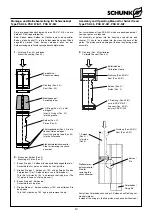
Befestigung des Schwenkkopfes
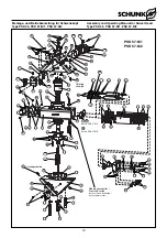
(Pos.-Nr. siehe Kapitel 12. Explosionszeichnung)
Zur Befestigung des Schwenkkopfes stehen im Anschraubwinkel
(Pos.19) 6 Durchgangsbohrungen Ø 10,5 zur Verfügung. Die
zwei Mittleren sind mit Paßsenkungen zur Aufnahme von
Zentrierhülsen versehen (PSK 45 Ø 14
H7
, PSK 57-N Ø 18
H7
).
Zur Befestigung werden im Beipack 4 Zylinderschrauben
(Pos. 65) sowie 2 Zentrierhülsen (Pos. 28) und beim PSK 57-N
zusätzlich Unterlegscheiben (Pos. 53) mitgeliefert.
Montage der Adapterplatten an den Schwenk-
körper
Adapterplatten werden entweder direkt an den 6 Innengewinden
in den Schwenkkörperanschraubflächen befestigt (PSK 45 M10,
PSK 57-N M12) oder mit den Durchgangsschrauben (Pos. 64)
aus dem Beipack.
Zur Zentrierung sind 2 Paßsenkungen (PSK 45 Ø 14
H7
, PSK 57-
N Ø 18
H7
) und die Zentrierhülsen (Pos. 28) aus dem Beipack vor-
gesehen. Verwenden Sie beim PSK 57-N zusätzlich die
Unterlegscheiben (Pos. 53).
3.
Scope of delivery
– Swivel Head PSK 45, PSK 57-N/1 oder PSK 57-N/2
(without adaptor plate and proximity switches)
– Little plastic bag: (see also chapter 12.2)
6 Centering sleeves (for fixing)
8 Cylinder screws (for fastening attachments)
4 Cylinder screws (for fastening the swivel head)
12 Discs (only for PSK57-N for fastening)
16 Set screws (f. closing connections which are not required)
16 O-rings (for direct connection without hoses)
2 O-rings 5 x 1,5 (for clamping proximity switches)
ACCESSORIES: (for a separate order, see catalog)
– Proximity switches
– Adaptor plates
4.
Technical data
(see catalog)
NOTE:
Before operation, please check if your case of application was
calculated by means of the “SCHUNK calculation program selec-
tion system for Swivel Units”. If not, the customer has no right to
claim for guarantee for this application.
– The airborne noise emitted by the swivel head is
≤
70 dB (A)
5.
Assembly
CAUTION!
Before mounting the swivel head unplug the machi-
ne or otherwise remove the power source. Please
observe the safety instructions on pages 3 and 4.
Fastening of the swivel head
(For Pos.-No. see chapter 12. Drawings)
For fastening of the swivel head an angular backplate (Pos. 19) 6
through bores Ø 10.5 are available. The 2 through bores in the
middle are equipped with countersunks for mountng of centering
sleeves (PSK 45 Ø 14
H7
, PSK 57-N Ø 18
H7
).
For fastening, 4 cylinder screws (Pos. 65) as well as 2 centering
sleeves (Pos. 28) out of the little plastic bag can be used.
For PSK 57-N washers (Pos. 53) are also included in the little
plastic bag.
Assembly of adaptor plates at the swivel body
Adaptor plates are directly mounted at the 6 internal screw
threads inside the screwed surface of the swivel body (PSK 45
M10, PSK 57-N M12) or with the through bolts (Pos. 64) out of
the little plastic bag.
For centering purposes, the units are equipped with 2 sunk fit-
tings (PSK 45 Ø 14
H7
, PSK 57-N Ø 18
H7
) and the centering slee-
ves (Pos. 28) out of the little plastic bag. In cases of PSK 57-N
please also use the washers (Pos. 53).


