Assembly
24
13.00 | PGB | Assembly and Operating Manual | en | 389275
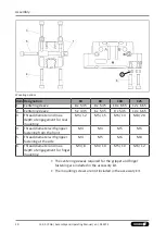
4.2.2 Turn control cam
Turn control cam, example control cam for inductive monitoring
Depending on the jaw stroke, it may be necessary to change the
alignment of the control cam for the sensors IN 80 and RMS 80.
In the image, the installation situation (A) shows the control cam
in the delivery state of the product and the installation situation
(B) shows the turned control cam.
In order to change the alignment of the control cam, proceed as
follows:
1. Undo the screw (2).
2. Remove control cam (1) from the product, turn and re-insert it
into the product.
3. Turn the screw (3) to push the position of the control cam (1).
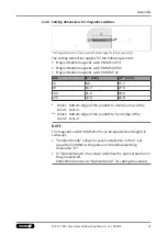
4.2.3 Switch-off hysteresis for magnetic switches
Sensors MMS 22, MMS 22-PI1, MMS 22-PI2 and MMS-P 22
The smallest detectable difference in stroke is defined in the
following table:
The smallest detectable difference in stroke based on the nominal stroke
For products with X mm
nominal stroke per jaw
Min. query range per jaw/
min. queried stroke difference per jaw
X ≤ 5 mm
30 % of the nominal stroke per jaw
X > 5 mm to X ≤ 10 mm
20 % of the nominal stroke per jaw
X > 10 mm
10 % of the nominal stroke per jaw
Example:
Product with 7 mm nominal stroke per jaw
7 mm * 20% = 1.4 mm


