background image

4

Prior to Installation

VENTILATION

It is very important that sufficient air for combustion is provided to the room containing the 
appliance, to enable correct and efficient working of the system. Reference should be made to 
the appliance manufacturer’s instructions
and recommendations are also given in the Building Regulations Document J.

CARBON MONOXIDE ALARMS

The carbon monoxide alarms should comply with BS EN 50291:2001.
Where a new or replacement fixed solid fuel appliance is installed in a dwelling, a carbon monoxide 
alarm must be provided in the room where the appliance is located.
Please follow manufacturer’s instructions with regard to siting and fixing or alternatively:-
a) On the ceiling at least 300mm from any wall or if it is located on a wall, as high up as possible 
(above any doors
and windows), but not within 150mm of the ceiling and
b) between 1m and 3m horizontally from the appliance.
N.B Provision of a carbon monoxide alarm should not be regarded as a substitute for correct 
installation and regular servicing.

HANDLING

It is advised that suitable PPE should be used when handling the products.

DELIVERY TO SITE AND STORAGE

Components should be carefully transported and off loaded. They should be inspected to ensure 
they have not been damaged, and should be stored off the ground and under cover so that they 
are protected from accidental damage and the adverse effects of weather. Particular care and 
attention should be taken to avoid surface damage to product with the high temperature painted 
finish.

Summary of Contents for Prima Smooth

Page 1: ...R REWARDS www schiedel com uk DON T FORGET TO REGISTER YOUR INSTALLATIONS AND START EARNING SCHIEDEL INSTALLER REWARDS See inside for more details Prima Smooth Installation Instructions SAP Issue 2 940002244 April 2019 ...

Page 2: ...e 18 Page 18 Page 19 Page 19 Max offset info Component weights After Installation Testing and commissioning prior To first use Appliance operation Multi fuel applications Maintenance Fuel storage and usage Notice plate Product warranty Product registration form Qr for installation assistant App download Qr link for online High Temperature Applications High Temperature Applications Connecting Flue ...

Page 3: ...N 1856 2 Connecting Flue Pipes and Chimney Liners BS EN 1859 Metal Chimneys Testing Methods BS EN 1443 Chimneys General Requirements BS EN 15287 1 Chimneys Design installation and commissioning of chimneys Chimneys for non room sealed heating appliances Approved Document J Combustion appliances and fuel storage systems England Wales DFP Technical Booklet L Combustion appliances and fuel storage sy...

Page 4: ...fixing or alternatively a On the ceiling at least 300mm from any wall or if it is located on a wall as high up as possible above any doors and windows but not within 150mm of the ceiling and b between 1m and 3m horizontally from the appliance N B Provision of a carbon monoxide alarm should not be regarded as a substitute for correct installation and regular servicing HANDLING It is advised that su...

Page 5: ...or a flue diameter smaller than the appliance spigot then the operational requirements of the appliance and the configuration of the flue must satisfy the flue sizing requirements of EN13384 1 DISTANCE TO COMBUSTIBLES In accordance with building regulations it is essential that the correct distance to combustible material is maintained On solid fuel applications where there is a risk of soot fire ...

Page 6: ... 6 for full details Within a system Chimney Connecting Flue Pipe there should be no more than 4 changes of direction of maximum 45 90 Factory made bends or tees within the system may be treated as being equal to two 45 bends as per Document J of the Building Regulations issued October 2010 INSPECTION On solid fuel applications to conform to Building Regulations provisions should be made to enable ...

Page 7: ...ing Access Twin Wall Chimney System Solid Wall Inspection Bend Wall Sleeve Trim Collar 600 min 225 For minimum distance for this configuration check manufacturers distance to combustibles No further bends allowed on this configeration Wall Band 450mm MAX REAR OUTLET SINGLE WALL CONNECTING FLUE PIPE INTO RE LINED MASONRY CHIMNEY Wall Sleeve Trim Collar 100 100 225 square 9 x 9 For minimum distance ...

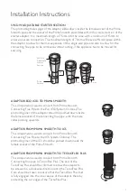
Page 8: ... Connection to the appliance can be done using either an appliance connector or a standard pipe or inspection pipe In both cases the male spigot should be pushed inside the appliance outlet The joint between the connecting flue pipe and the appliance should be securely caulked and sealed using non asbestos fibre rope or alternative and fire cement JOINT DETAIL Female Socket Male Spigot Direction o...

Page 9: ...component is used to convert from Prima Smooth Connecting Flue Pipe to the Eco ICID System Chimney The protruding liner of the adaptor should be pushed down inside the female socket of the connecting flue pipe with the male collar pointing upwards ADAPTOR FROM PRIMA SMOOTH TO ICS This component is used to convert from Prima Smooth Connecting Flue Pipe to the ICS System Chimney The protruding liner...

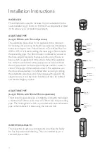
Page 10: ...the adj pipe down inside the previous pipe until the socket is clear of the spigot of the adaptor above it The appliance can then be removed safely It is refitted after servicing by sliding the adjustable pipe back up to fully engage with spigot of the adaptor above it and the cover band should then be refitted and fastened tightly in place Max Adj 70mm 50mm Engagement Bead Adj Pipe Standard Pipe ...

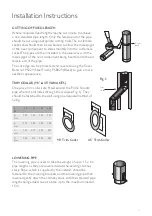
Page 11: ...in the usual way with the male spigot of the next component being inserted into thecut female end of the pipe The cut edge can be protected and covered using the Cover Band ref PS029 Steel Finish PSB029 Black to give a more aesthetic appearance Cover Band Trim Collar Fig 1 90 Trim Collar 45 Trim Collar A B B D C A Int Ø 125 150 180 200 A mm 129 154 184 204 B mm 275 300 330 350 C mm 181 215 259 287...

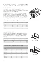
Page 12: ... the cantilever brackets using the bolts provided through the fixing slots in the top plate CANTILEVER SUPPORT Once the position of the support has been established within the chimney stack secure the cantilever brackets to the wall using expansion bolts to ensure adequate attachment and support 90 A B C D 243 A B A B Type 570 Types 325 475 Int Ø 125 150 180 200 A mm 185 210 240 260 B mm 221 246 2...

Page 13: ...t plate bedding down firmly into the cement at the top of the masonry stack The joint between the plate and the adjustable pipe length should be sealed using an appropriate high temperature sealant Once securely in place the plate should be flaunched to make weatherproof RAINCAP The raincap is of standard Prima Plus design The male spigot is pushed down inside the female form of the expansion join...

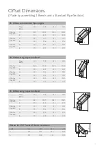
Page 14: ...4 74 74 C 100 100 100 100 45 Offset using Inspection Bend Int Ø 125 150 180 200 A 415 415 415 415 B 138 138 138 138 C 94 94 94 94 Offsets 45 Int Ø 125 150 180 200 A 333 333 333 333 B 138 138 138 138 A C B A C B A B A B A E f f P i p e B 30 Offset with standard Pipe lengths Nom Ømm 125 150 180 200 Effective Pipe 950 A 1099 1099 1099 1099 B 549 549 549 549 Effective Pipe 450 A 666 666 666 666 B 299 ...

Page 15: ...ng Inspection Bend Nom Ømm 125 150 180 200 Effective Pipe 950 A 1230 1230 1230 1230 B 549 549 549 549 Effective Pipe 450 A 797 797 797 797 B 299 299 299 299 Effective Pipe 200 A 580 580 580 580 B 174 174 174 174 A B A B E f f P i p e 45 Offset using Inspection Bend Nom Ømm 125 150 180 200 Effective Pipe 950 A 1087 1087 1087 1087 B 810 810 810 810 Effective Pipe 450 A 733 733 733 733 B 456 456 456 ...

Page 16: ...oth to TecnoFlex Plus Steel PS0E3 TecnoFlex Plus Liner Inspection Pipe PSB012 Appliance Connector PSB013 Inspection Elbow PSB044 Appliance Connector PSB013 Expansion Joint PS031 Raincap Locking Band S036 S030 Stove Adaptor PS013 Pipe PS003 Support Plate PS0F1 Lowering Pipe PS333 Cantilever Support Type 325 95420001 SW DW Stove Pipe Starter Section Eco ICID DN8A152 Inspection Pipe PSB012 Min 425mm ...

Page 17: ... Ø 125 200 X m 1 5 Y m 1 Approximate Weights of Finished Goods Kg Prima Smooth 0 6 mm Internal Diameter Length mm 1000 500 250 125mm 1 82 0 91 0 46 150mm 2 28 1 14 0 57 180mm 2 72 1 36 0 68 200mm 3 02 1 51 0 76 Prima Smooth 1 mm 125mm 3 03 1 5 0 77 150mm 3 8 1 9 0 95 180mm 4 54 2 27 1 13 200mm 5 04 2 52 1 26 ...

Page 18: ...imney system should be carried out at least once a year along with maintenance of the appliance but it is recommended that chimneys serving solid fuel appliances be swept at least twice a year at the end of the heating season to remove any deposits which may have built up during the season and prior to the start of the next heating season to ensure that the the flue way is clear of any blockages s...

Page 19: ...due to defective materials or faulty manufacture Schiedel Chimney Systems undertake to replace the product only Schiedel Chimney Systems cannot accept liability nor take any responsibility for the installation building or redecorating costs or any other consequential losses arising If any complaint is found to be a result of faulty installation non compliance with or abuse contrary to these condit...

Page 20: ... of the installation process from connection to the appliance through to termination Highlighting the safety critical areas where the chimney penetrates the floors ceilings roof and walls Incorporates frequently asked questions information at each stage of the installation process in line with building regulations An easy to use system for downloading full product information and installation inst...

Reviews: