9 Infrared connection
Operating Manual 90° ACTUSAFE CMF(S)QT
OM-ENGLISH-Failsafe-QT-16xx-V2.00-2022.03.01
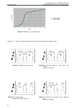
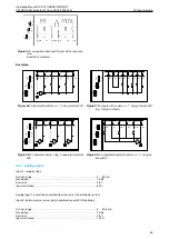
Figure 84:
Example for a history entry.
9
Infrared connection
For easier communication and better visualization of the menu options, the unit provides an infrared port for connection to
a PC.
The required hardware (connection cable to the PC’s RS-232 or USB connectors) and the corresponding software are
available as options.
The SMARTTOOL software, in addition to communication with the actuator, allows the management of multiple actuators
to transfer the configuration to different actuators.
This approach can greatly simplify operation.
Please refer to the SMARTTOOL software operating instructions manual for further information.
During operation, it must be ensured that the IR interface surface is protected from strong disturbances which may other-
wise compromise the communication.
Before mounting the infrared adapter, clean the surface of the infrared interface with a damp cloth.
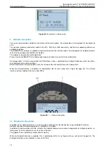
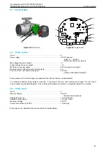
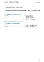
When the infrared interface is enabled, it is indicated by LED L5 (see section 6.2.2, Figure 85, page 35). The infrared
interface can be enabled in the menu item P20.6.
Figure 85:
1. . . Infrared connection
10
Bluetooth connection
In addition to the infrared interface, it is also possible to configure the Control System using a Bluetooth interface.
Software required for Android equipment is available as an option.
In addition to communication with the actuator, the Android software also enables management of multiple actuators, al-
lowing easy transfer of parameter sets to various actuators.
This approach can significantly simplify commissioning.
When the Bluetooth interface is enabled, this is indicated by LED L5 (see Figure 85 resp. section 6.2.2, page 35). The
Bluetooth interface can be enabled in menu item P20.6.
74

