background image


B1051039 Rev. B 

USBCam


34 

Immunity Test 

IEC 60601 Test 

Level 

Compliance 

Level 

Guidance 

a

 Field strengths from fixed transmitters, such as base stations for radio (cellular/cordless) telephones and land 

mobile radios, amateur radio, AM and FM radio broadcast and TV broadcast cannot be predicted theoretically with 
accuracy. To assess the electromagnetic environment due to fixed RF transmitters, an electromagnetic site survey 
should be considered.  If the measured field strength in the location in which the USBCam is used exceeds the 
applicable RF compliance above, the USBCam should be observed to verify normal operation.  If abnormal 
performance is observed, additional measures may be necessary, such as reorienting or relocating the USBCam. 
 

b

 Over the frequency range 150 kHz to 80 MHz, field strengths should be less than 3 V/m 


Table 7. Recommended Separation Distance Between Portable and Mobile RF 

Communications Equipment and the USBCam System 

PLEASE NOTE: The USBCam is intended for use in an electromagnetic environment in which radiated RF disturbances 
are controlled. The USBCam user can help prevent electromagnetic interference by maintaining a minimum distance 
between portable and mobile RF communications equipment (transmitters) and the system as recommended below, 
according to the maximum output power of the communications equipment.


Rated maximum output 

power of the transmitter 

(W) 

Separation distance according to the frequency of the 

transmitter (m) 


150 kHz to 800 MHz 
d=1.17x

800 MHz to 2.5 GHz 

d= 2.3 x 

0.01 

 0.12 

 0.23 

0.1 0.37  

0.73 

1 1.17 


2.30 

10 3.69  

7.27 

100 11.7   

23.00 

For transmitters rated at a maximum output power not listed above, the recommended separation distance d in 
meters (m) can be estimated using the equation applicable to the frequency of the transmitter, where P is the 
maximum output power rating of the transmitter in watts (W) according to the transmitter manufacturer. 
NOTE 1: At 800 MHz, the separation distance for the higher frequency range applies. 
NOTE 2: These guidelines may not apply in all situations.  Electromagnetic propagation is affected by absorption 
and reflection from structures, objects, and people. 


Summary of Contents for USBCam

Page 1: ...e folder named USBCam Driver and copy its contents to your TempDrivers folder 4 Continue with the USBCam Device Drivers installation section for your particular operating system When you are prompted for the location of the drivers point the installation wizard to the TempDrivers folder For Windows 98 Second Edition continue with Section 3 4 3 For Windows 2000 continue with Section 3 5 3 For Windo...

Page 2: ......

Page 3: ...USBCam User Guide Schick Technologies Inc 30 00 47th Avenue Long Island City NY 11101 718 937 5765 718 937 5962 fax PART NUMBER B1051039 REV B ...

Page 4: ...ocument was originally prepared in English Many of the designations used by manufacturers and sellers to distinguish their products are claimed as trademarks Where those designations appear in this document and Schick Technologies Inc was aware of a trademark claim the designations have been printed in caps or initial caps ...

Page 5: ...ith Windows 2000 13 3 6 Setup with Windows XP 19 4 Operation 24 4 1 Operating the Camera 24 4 2 Using Camera Sheaths 25 4 3 Using the Camera with CDR 26 4 4 Acquiring Video Images with the Footpedal 28 4 5 Acquiring Video Images with Keyboard Shortcuts 28 5 Protective Measures 29 5 1 Sheaths 29 5 2 Handpiece and Lens 29 5 3 Computer 29 Appendix A Reference Information 30 A 1 Removal and Replacemen...

Page 6: ...ble 3 Keyboard Shortcuts 28 Table 4 Specifications 30 Table 5 Guidance and Manufacturer s Declaration Electromagnetic Emissions 32 Table 6 Guidance and Manufacturer s Declaration Electromagnetic Immunity 32 Table 7 Recommended Separation Distance Between Portable and Mobile RF Communications Equipment and the USBCam System 34 Table 8 Setup Dialog Box Description 36 Table 9 Camera Properties Dialog...

Page 7: ... Considerations Although the USBCam equipment is designed to provide a reasonable degree of protection from electromagnetic interference according to IEC International regulations it must be installed at an adequate distance from electricity transformer rooms static continuity units two way amateur radios and cellular phones To ensure proper operation the latter can be used only at a minimum dista...

Page 8: ...B1051039 Rev B USBCam iv USBCam USBCam with Handpiece Holder ...

Page 9: ... Camera Sheaths 1 3 Getting the Best Images with Your USBCam Getting the best results from your USBCam begins with having a computer system suitable for displaying and capturing video images For optimum performance we recommend a PCs equipped with Pentium III processors or higher b minimum 8MB video memory and c display values for your monitor set at least to 800 x 600 x 24 bit color We also recom...

Page 10: ...ontrols Table 1 Description of Camera Controls Number Description Camera lens and LED light emitting diode source Freeze frame button set to Freeze Unfreeze or Freeze Take option Power on off button See Note 1 Quick disconnect for portability See Note 2 NOTE 1 Light source will automatically time out after 4 5 minutes of continuous operation NOTE 2 B connector end of USB cable connects here ...

Page 11: ...the other The A type plug connects to any available USB port on the computer The B type plug connects to the handpiece Figure 2 USB Cable Connectors 2 2 Installing the USBCam Handpiece Holder The USBCam Handpiece Holder turns off the camera when the handpiece is inserted and turns on the camera when the handpiece is removed The holder is equipped with several mounting options 1 Can be mounted to a...

Page 12: ...dpiece from its holder before performing this procedure 2 Remove the cutout block from the handpiece holder by loosening 2 flat head Phillips screws 3 Position the holder on a smooth stable vertical surface Using the holes on the back of the holder as guides fasten the holder securely to the wall using 2 6 x 3 4 dry wall screws not supplied or other hardware appropriate to the mounting surface 2 2...

Page 13: ...ePageatthebeginningof this UserGuide The software for your USBCam consists of the following components A CDR Video Manager for DirectX Installation B DirectX Update C USBCam Device Driver Installation USB device driver Composite video driver Audio driver 2 You must install each of these components successfully to ensure proper operation of your USBCam Actual installation differs slightly between o...

Page 14: ...the Windows desktop and insert the CD The CD should install the CDR setup program automatically If it doesn t click the Start button and then on Run When the Run dialog box opens type d cdrsetup setup if d is the drive letter for your CD ROM drive If your CD ROM drive uses a different letter type in that one instead Then read and follow the instructions on each screen When you re all done remove t...

Page 15: ...ectX disk Setup should start automatically If it doesn t click Start Run and then enter d setup setup at the command line if your CD drive is a letter other than d use that letter instead B Click Install CDR Video Manager to begin the setup process STEP 2 Click Next STEP 3 A Select the CDR camera you will be using By default USBCam is selected B Click Next ...

Page 16: ...s as you will need this information during the Add New Hardware wizard in Section 3 4 3 C Click OK STEP 6 When the new video series is installed click OK STEP 7 A Make sure the checkbox Yes I want to update DirectX on my system is marked B Click Finish which will automatically start the setup program to update DirectX files on your system C Continue with Section 3 4 2 Installing DirectX Drivers ...

Page 17: ...d agreeing with the terms of the license STEP 2 A Click Install when prompted by the setup program B The DirectX setup program will analyze your current version of DirectX and update files as needed STEP 3 A Click OK when setup is complete B When prompted click OK to restart your computer C Continue with Section 3 4 3 Installing USBCam Device Drivers ...

Page 18: ... USB Device CompositeVideo andAudio oneafteranother STEP 1 You will need the Windows 98 CD to complete the following procedure When prompted insert the Windows 98 CD ROM and follow the directions provided STEP 2 Connect the USBCam to your computer When you do you will receive a momentary message saying that Windows has detected new hardware PleaseNote This isthefirstdriverthat willbe installed STE...

Page 19: ...owse your system for the USBCam drivers that were installed on your system during Section 3 4 1 Installing CDR Video Manager for DirectX Non CDR users please browse to your USBCam driver folder as described in the Notice Page at the beginning of this document B Click Next STEP 6 A When Windows finds the appropriate driver it prompts you to confirm it B Click Next ...

Page 20: ...te Windows willautomatically begin locatingthenext driver A You will be prompted through screens similar to the ones in Steps 3 through 7 B When you reach the last screen remove the Windows 98 CD and click Finish C If the Windows 98 CD setup program begins just cancel setup and remove the Windows 98 CD D Click the Exit button on the USBCam Setup page and remove the CD ...

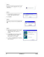
Page 21: ...isk Setup should start automatically If it doesn t click Start Run and then enter d setup setup at the command line if your CD drive is a letter other than d use that letter instead B Click Install CDR Video Manager to begin the setup process STEP 2 Click Next STEP 3 A Select the CDR camera you will be using By default USBCam is selected B Click Next ...

Page 22: ...ed this information during the Add New Hardware wizard in Section 3 5 3 Installing USBCam Device Drivers C Click OK STEP 6 When the new video series is installed click OK STEP 7 A Make sure the checkbox Yes I want to update DirectX on my system is marked B Click Finish which will automatically start the setup program to update DirectX files on your system C Continue with Section 3 5 2 Installing D...

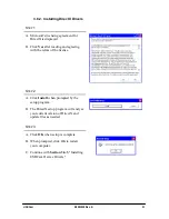
Page 23: ...nd agreeing with the terms of the license STEP 2 A Click Install when prompted by the setup program B The DirectX setup program will analyze your current version of DirectX and update files as needed STEP 3 A Click OK when setup is complete B When prompted click OK to restart your computer C Continue with Section 3 5 3 Installing USBCam Device Drivers ...

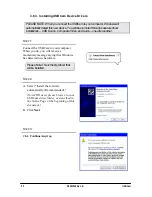
Page 24: ...throughseparatedriver installations USB Device CompositeVideo andAudio oneafteranother STEP 1 Connect the USBCam to your computer When you do you will receive a momentary message saying that Windows has detected new hardware PleaseNote This isthefirstdriverthat willbe installed STEP 2 Click Next STEP 3 A Select Search for a suitable driver for my device recommended B Click Next ...

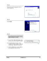
Page 25: ... Installing CDR Video Manager for DirectX Non CDR users please browse to your USBCam driver folder as described in the Notice Page at the beginning of this document B Click Next STEP 5 A When Windows finds the appropriate driver it prompts you to confirm it B Click OK STEP 6 A Windows is ready to install the driver you selected and will prompt you to install it B Click Next ...

Page 26: ...s STEP 8 Click Finish STEP 9 PleaseNote Windows willautomatically begin locatingthenext driver A You will be prompted through screens similar to the ones in Steps 2 through 8 B Click the Exit button on the USBCam Setup page and remove the CD ...

Page 27: ...sk Setup should start automatically If it doesn t click Start Run and then enter d setup setup at the command line if your CD drive is a letter other than d use that letter instead B Click Install CDR Video Manager to begin the setup process STEP 2 Click Next STEP 3 A Select the CDR camera you will be using By default USBCam is selected B Click Next ...

Page 28: ...em it has copied the drivers B Click OK STEP 6 When the new video series is installed click OK STEP 7 A Make sure the checkbox Yes I want to update DirectX on my system is marked B Click Finish which will automatically start the setup program to update DirectX files on your system C Continue with Section 3 6 2 Installing DirectX Drivers ...

Page 29: ...nd agreeing with the terms of the license STEP 2 A Click Install when prompted by the setup program B The DirectX setup program will analyze your current version of DirectX and update files as needed STEP 3 A Click OK when setup is complete B When prompted click OK to restart your computer C Continue with Section 3 6 3 Installing USBCam Device Drivers ...

Page 30: ...ndAudio oneafteranother STEP 1 Connect the USBCam to your computer When you do you will receive a momentary message saying that Windows has detected new hardware PleaseNote This isthefirstdriverthat willbe installed STEP 2 A Select Install the software automatically Recommended Non CDR users please browse to your USBCam driver folder as described in the Notice Page at the beginning of this documen...

Page 31: ...leaseNote Windows willautomatically begin locatingthenext driver A You will be prompted through screens similar to the ones in Steps 2 through 5 B When all of the drivers have been installed Windows displays a message confirming a completed installation C Click the Exit button on the USBCam Setup page and remove the CD ...

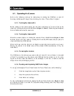
Page 32: ...mera in its holder to protect the device and for easy access Placing the camera in its holder turns off the camera LEDs automatically if they are illuminated 4 1 3 Focusing the Camera The USBCam is a fixed focus type camera with an 8 mm 0 31 in to 40 mm 1 6 in depth of field To accurately focus the camera start CDR and turn the camera on As live video begins to stream adjust the distance of the ha...

Page 33: ...treaming video To capture an image when live video is paused click the Take button on the Video Capture window Figure 4 Video Window Setup and Capture Buttons 4 2 Using Camera Sheaths Disposable sheaths are provided with each USBCam System as an effective measure for ensuring proper hygiene and to protect against infectious disease Use a new sheath for each intra oral use and then dispose it of pr...

Page 34: ...ck on Video Exam You may use a pre defined video series or create a new one B If you choose to create a new video series click Edit Series which opens the New Custom Video Series dialog box The numbers in the text boxes correspond to how many target frames are included in this series You can edit the numbers in the text boxes creating a series customized with the views you wish to include C Enter ...

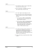
Page 35: ... button captures the image Continue with Step 7 2 If you set up your USBCam for Freeze Unfreeze pressing the Freeze Frame button pauses live video To resume streaming video press the Freeze Frame button again To capture an image click the Take button on the Video Capture window Continue with the next step STEP 7 A The captured video image appears in either the exam or zoom window depending on sett...

Page 36: ...mage Green Still Image is frozen in video window Unfreeze Image Amber 4 5 Acquiring Video Images with Keyboard Shortcuts Video image acquisition can be also accomplished though the use of shortcut keys To use the following shortcuts press and hold down the first key always the Alt key and then press the second key shown after the plus sign for the appropriate action Table 3 Keyboard Shortcuts Vide...

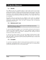
Page 37: ...718 937 5765 5 2 Handpiece and Lens IMPORTANT Be sureto disconnect thecamerafromitsUSBcableandportbefore performinganycleaningprocedures To clean and disinfect the handpiece use a clean lint free cloth and a small amount of alcohol Do not soak the handpiece and be sure to dry it completely Before cleaning the lens be certain that it is free of any abrasive contaminants This will help to avoid the ...

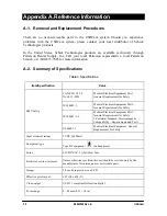
Page 38: ...ical Electrical Equipment Part 1 General Requirements for Safety IEC60601 1 Medical Electrical Equipment Part 1 General Requirements for Safety IEC60601 1 2 Medical Electrical Equipment Part 1 General Requirements for Safety 2 Collateral Standard Electromagnetic Compatibility Requirements and Tests EMC Safety UL60601 1 Medical Electrical Equipment General Requirements for Safety Input electrical r...

Page 39: ...equirements of IEC 60601 1 1 safety standard Variations however may exist in the construction of computers to which the USBCam is connected Users are advised to have a qualified electrician perform a leakage test on their equipment before using the USBCam A 4 Handpiece Product Label Information The following product label information can be found on the USBCam handpiece An ESD symbol also appears ...

Page 40: ...601 Test Level Compliance Level Guidance Electrostatic discharge ESD IEC 61000 4 2 6 kV contact 8 kV air 6 kV contact 8 kV air Floors should be wood concrete or ceramic tile If floors are covered with synthetic material the relative humidity should be at least 30 To avoid damage to electronic components inside users should not touch the exposed USBCam connector before discharging to an earthed obj...

Page 41: ...the frequency of the transmitter Recommended separation distance d 1 2 P Radiated RF IEC 61000 4 3 3 V m 80 MHz to 2 5 GHz 3 V m d 1 2 P for 80 MHz to 800Mhz d 2 3 P for 800 MHz to 2 5Ghz Where P is the maximum output rating of the transmitter in watts W according to the transmitter manufacturer and d is the recommended separation in meters m Field strengths from fixed RF transmitters as determine...

Page 42: ...ntended for use in an electromagnetic environment in which radiated RF disturbances are controlled The USBCam user can help prevent electromagnetic interference by maintaining a minimum distance between portable and mobile RF communications equipment transmitters and the system as recommended below according to the maximum output power of the communications equipment Rated maximum output power of ...

Page 43: ... quality and performance is also affected by the amount of video memory available By running diag exe as documented below and checking the Display tab you can verify the amount of video memory available on your graphics card STEP 1 A At the Windows desktop click Start Run and then type dxdiag exe B The DirectX Diagnostic Tool dialog box is displayed C Under the System tab verify that your current ...

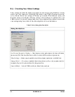
Page 44: ...nge them they can be adjusted using options found on the video setting dialog boxes Refer to the following tables for more information Table 8 Setup Dialog Box Description Dialog Box Options Use Preview Stream for Display May improve video performance for slower Pentium processors PII This checkbox has no effect on faster PIII and above processors Video Settings More camera operation and video dis...

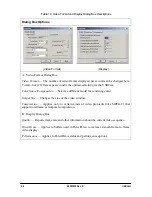
Page 45: ...ideo frames displayed per second If changes in frame rate are required do not change them here but in the Video Format dialog box Table 10 Image Modes Adjusts the orientation Mirror or the appearance of darker areas on the displayed image Backlight Compensation White Balance Adjusts color levels of video images to compensate for environmental lighting conditions Flickerless Compensates for display...

Page 46: ...Color Space Compression Selects a different model for rendering color Output Size Changes the size of the video window Compression Applies only to certain kinds of video protocols like MPEG 2 that support interframe or temporal compression B Display Dialog Box Quality Reports frame rate and other information about the current video sequence DirectDraw Applies to buffers used in DirectDraw to incre...

Reviews: