Schäfter+Kirchhoff SK6288VKOC-4L Instruction Manual Download Page 27

Advanced SkLineScan Software Functions

Instruction Manual

 SK6288VKOC-4L


SK6288VKOC-L_CameraContr

ol(4)_ByCommands.indd

27

Instruction Manual SK6288VKOC-4L    © 2018-04 E
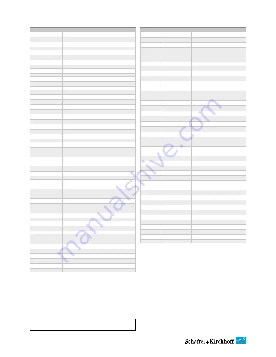
 

„

Set Commands

Set Operation

Description

G

oooo

<CR>

gain 1 (red odd)  setting 0-24 dB 

B

oooo

<CR>

gain 2 (red even)  setting 0-24 dB 

H

oooo

<CR>

gain 3 (green odd)  setting 0-24 dB 

O

ppp

<CR>

offset 1 (red odd)  setting

P

ppp

<CR>

offset 2 (red even)  setting

Q

ppp

<CR>

offset 3 (green odd)  setting

F24<CR>

output format:  3x 8 bit video data

C30<CR>

camera clock:  30 MHz data rate 

C60<CR>

camera clock:  60 MHz data rate

T0<CR>

test pattern off / SCM off

T1<CR>

test pattern on (turns off with power off)

T2<CR>

shading correction on

T3<CR>

auto program Shading Correction / SCM on

T4<CR>

copy flash memory 1 to SCM

T5<CR>

save SCM to flash memory 1

T6<CR>

video out = SCM data

T7<CR>

copy Flash Memory 2 to LUT Memory

T8<CR>

save LUT Memory  to Flash Memory 2

T9<CR>

Video out = LUT data

M0<CR>

line trigger mode0: internal all lines

M1<CR>

line trigger mode1: extern trigger, next 
line

M2<CR>

line trigger mode0: internal all lines and set 
max line rate  

M4<CR>

line trigger mode4: extern trigger and restart

M5<CR>

line trigger mode5: extern SOS, all Lines

A

xxxx

<CR>

SCM address (xxxxx = A0-A6287) or LUTM 
(xxxxx = A32768-A36863)

D

xxxx

<CR>

SCM data (

xxxx

 = 0-4095) and increment  

SCM address

E

yyyyy

<CR>

frames / multiframe  (

yyyyy

 = 0-32767)  

EF

yyyyy

<CR>

external frame trigger delay 
(

yyyyy

 = 0-32767 lines) 

N

yyyyy

<CR>

lines / frame  (

yyyyy

 = 1-32767)  

SLUT<CR>

enable LUT

RLUT<CR>

disable LUT

W

yyyyy

<CR>

line clock frequency 
(

yyyyy

 = 50-9259)  (Hz)

WL

yyyyy

<CR>

Window Pixel length (

yyyyy

 =1-Line length)

WF

yyyyy

<CR>

Window First Pixel  (

yyyyy

 = 1-Line length)

X

yyyyy

<CR>

exposure time (

yyyyy

 = 10-20000)  (µs)

V

yyyyy

<CR>

extern sync divider  (

yyyyy

 = 1-32767)  

Y

ppp

<CR>

set  sync control  (

ppp

 = 255) 


„

Request Commands

Request

Return 

Description

K<CR>

SK6288VKOC-4L


returns S

K

 type number

R<CR>

Rev2.35

returns 

R

evision number

S<CR>

SNr00163


returns 

S

erial number

I<CR>

SK6288VKOC-4L
Rev2.35
SNr00163

camera identification readout

I1<CR>

VCC: 

yyyyy


returns VCC (1=10mV)

I2<CR>

VDD: 

yyyyy

returns VDD (1=10mV)

I3<CR>

moo: 

yyyyy

returns mode of operation

I4<CR>

CLo: 

yyyyy

returns camera clock low 
frequency (MHz)

I5<CR>

CHi: 

yyyyy

returns camera clock high 
frequency (MHz)

I6<CR>

Ga1: 

yyyyy

returns gain 1

I7<CR>

Ga2: 

yyyyy

returns gain 2

I8<CR>

Of1: 

yyyyy

returns offset 1

I9<CR>

Of2: 

yyyyy

returns offset 2

I10<CR>

Ga3 

yyyyy

returns gain 3

I12<CR>

Of3: 

yyyyy

returns offset 3

I19<CR>

Tab: 

yyyyy

returns video channels

I20<CR>

CLK: 

yyyyy

returns selected clock 
frequency (MHz)

I21<CR>

ODF: 

yyyyy

returns selected output data 
format

I22<CR>

TRM: 

yyyyy

returns selected trigger mode

I23<CR>

SCO: 

yyyyy

returns shading corr. on/off

I24<CR>

Exp: 

yyyyy

returns exposure time

I25<CR>

miX: 

yyyyy

returns min. exposure time (µs)

I26<CR>

LCK: 

yyyyy

returns line frequency  (Hz)

I27<CR>

maZ: 

yyyyy

returns max. line frequency 
(Hz)

I28<CR>

TSc: 

yyyyy

returns Sync Divider 

I29<CR>

SyC: 

yyyyy

returns Sync Control 

I30<CR>

Lin: 

yyyyy

returns Lines/Frame 

I31<CR>

DXT: 

yyyyy

returns DXT on/off

I32<CR>

Tmp: 

yyyyy

returns Video Board Temper.

I33<CR>

FSD: 

yyyyy

returns Frame Trigger Delay

I36<CR>

WPL: 

yyyyy

returns Window Pixel length

I37<CR>

WFP: 

yyyyy

returns Window First Pixel

I38<CR>

LUT: 

yyyyy

returns LUT on/off

I39<CR>

KST: 

yyyyy

returns Status

Range of values:

oooo

  = 0 ... 1023

ppp


= 0 ... 255

xxxx


= 4 digits integer value as ASCII

yyyyy

  = 5 digits integer value as ASCII

LUT: 

Lookup Table

SCM:  Shading Correction Memory

SOS:  Start of Scan

Acknowledgement for all set commands:

0 = OK,  1 = not OK

Summary of Contents for SK6288VKOC-4L

Page 1: ...ruction Manual SK6288VKOC 4L 3 2 Sample Configuration 1 CCD line scan camera SK6288VKOC 4L mounted with 2 Mounting bracket SK5105 L 3 Clamping claws SK5101 4 Focus adapter FA22R 45 two piece facilitates adjustment of any rotation angle 5 Enlarging lens Apo RodagonN4 0 80 5 4 1 400 500 700 800 600 Wavelength nm 0 Responsitivity V mJ cm2 100 0 0 1 0 400 500 600 Wavelength nm Relative sensitvity colo...

Page 2: ...k directly into the light beam w Mechanics Warning Ensure that the motion device and the scan way is free to move and that no obstacles are in the way Do not place any part of the body in the way of moving parts Line scan cameras are mostly used in combination with a motion device such as a translation stage a conveyer or a rotational drive as well as with high intensity light sources For assembly...

Page 3: ...ation SkLineScan Start up Camera Setup Initial Function Test 3 Camera Control and Performing a Scan 12 3 1 Software SkLineScan 12 Function Overview SkLineScan Toolbar Basic Visualization of the Sensor Output 3 2 Adjustments for Optimum Scan Results 14 Lens Focussing Sensor Alignment Gain Offset Adjustment White Balance and Shading Correction Integration Time Synchronization of the Imaging Procedur...

Page 4: ...e focus and aperture settings for evaluating field flattening of the lens and for orientation of the illumination and the sensor see 14 6 GigE Connections and SkLineScan Software Installation p 69 The Schäfter Kirchhoff GigE Vision line scan cameras implement a superset of the Gen I Cam specification which defines the device capabilities The settings made in the SkLineScan program are automaticall...

Page 5: ...for minimum system configuration black optional accessories For accessory order details see Accessories p 36 Motion unit with encoder Synchronization cable Power supply cable Gigabit Ethernet cable Computer Power supply unit Schäfter Kirchhoff SkLineScan adjustment and control software 3rd party software that supports the GEN i CAMTM standard Line scan camera Clamping claw Mounting bracket Optics ...

Page 6: ...nt M45x0 75 Flange focal length 19 5mm Weight 0 3 kg Operating temperature 5 45 C Introduction Instruction Manual SK6288VKOC 4L shared_SystemRequirements_Specs_ML indd 6 Instruction Manual SK6288VKOC 4L 2018 04 E 1 3 Computer System Requirements 1 4 SK6288VKOC 4L Line Scan Camera Specifications Introduction Intel Pentium Dual Core or AMD equivalent RAM min 4GB depending on size of acquired images ...

Page 7: ...e components are pre assembled and shipped as one unit Keep the protective cap on the lens until the mechanical installation is finished If you must expose the sensor or lens surface ensure the environment is as dust free as possible Gently blow off loose particles using clean compressed air The sensor and lens surfaces can be cleaned with a soft tissue moistened with water or a water based glass ...

Page 8: ...ra to a PC the maximum cable length is 100m The operating power must be supplied by an external source using socket 1 If you want to operate the camera in FREE RUN trigger mode the connections are complete with the CAT6 Ethernet cable and the connection to an external power supply For any kind of synchronized operation the external trigger signal s must be wired to socket 2 as well A frame synchro...

Page 9: ...udes a particular filter driver for the NIC Install the software package Commonly this will also cover the driver installation 2 The 3rd party software does not include a NIC filter driver and your NIC has an INTELPRO 100 chip Install the Pleora eBUS Optimal Driver 3 The 3rd party software does not include a NIC filter driver and your NIC has a different chip Keep the manufacturer driver and follo...

Page 10: ...nding on the installed Ethernet card and driver D C To Set the NIC IP address Start Control Panel Network Connections Right click Local Area Connection and select Properties The Local Area Connection Properties dialog appears Select Internet Protocol TCP IP and click Properties The Internet Protocol TCP IP Properties dialog appears Enable Use the following IP address and enter the following settin...

Page 11: ...can Setup dialog SkLineScan Start up Start SkLineScan A start up dialog box pops up and displays the connected cameras that have been automatically detected Desktop Icon 2 4 SkLineScan Software Installation Optional SkLineScan Installation Prior to the installation power on the PC not the camera and unpack the downloaded zip file to a temporary folder Alternatively if your installation medium is a...

Page 12: ...ain Offset Control dialog Click on the desktop icon to start the SkLineScan program The SkLineScan program recog nizes the connected line scan cameras automatically The identified cameras are shown in the start up dialog A and the index order corresponds with the individual MAC addresses of the cameras If the SK6288VKOC 4L camera is identified correctly confirm with OK The Signal window graphicaly...

Page 13: ...s with the number of pixels in the line sensor Zoom Function For high numbers of sensor pixels the limited number of display pixels might be out of range in which case the zoom function can be used to visualize the brightness profile in detail Magnification of one or several sections of the signal allows individual pixels to be resolved for a detailed evaluation of the line scan signal Window Spli...

Page 14: ...hieved most readily by shortening the integration time as described in section Integration Time p 19 Camera Control and Performing a Scan Instruction Manual SK6288VKOC 4L shared_CameraControl 2 _Adjustments 1_ML indd 14 Instruction Manual SK6288VKOC 4L 2018 04 E Lens focussing Sensor alignment Gain Offset Shading correction Integration time Synchronization of the sensor exposure and the object sur...

Page 15: ...set factory settings Open the Gain Offset Control dialog to re adjust or customize these settings Adjustment principle 1 Offset To adjust the zero baseline of the video signal totally block the incident light and enter 00 volts for channel1 For a two or multi channel sensor minimize any diffe rences between the channels by adjusting the other Offset sliders A slight signal noise should be visible ...

Page 16: ...rrection with a balanced RGB sensitivity ensures a natural color reading The reference signal is stored in the Shading Correction Memory SCM of the camera and subsequent scans are normalized using the scale factors from this white reference Step 1 White Balancing Use a homogeneous white object e g a white sheet of paper to acquire the RGB line signals Color line signal with separated RGB curves Wh...

Page 17: ...section Integration Time p 19 Check that the weakest color signal is higher than about 70 If necessary adjust the line frequency or the illumination intensity accordingly Tick the box Decoupling LF A in the Camera Control dialog Reduce the integration times for the two color channels with the higher signals in order to align the Red Green and Blue channels to the same level The Red channel is adju...

Page 18: ...h FL sensor length SL and field of view FOV according to your setup The implemented algorithm will compensate the natural lens vignetting Click on Save SCM to Flash to save the SCM reference signal in the flash memory of the camera Step 2 Obtaining the Shading Correction Data The shading correction refrence data that is stored in the shading correction memory SCM can be obtained in two ways Shadin...

Page 19: ... by using application programming interface API functions The relationshhip between the storage locations and the related API functions are shown in the diagram below The API functions are included in the SK91USB3 WIN software package See the SK91USB3 WIN manual for details Structure of the shading correction memories and the related API functions for memory handling Camera Control and Performing ...

Page 20: ... the CCD line scan camera To obtain a proportional image with the correct aspect ratio a line synchronous transport with the laterally correct pixel assignment is required The line frequency and the constant object velocity have to be coordinated In cases of a variable object velocity or particularly high accuracy requirements then an external synchronization is necessary The various synchronizati...

Page 21: ...ously exposed line FrameTrigger SK FrameSync The frame trigger synchronizes the acquisition of a 2D area scan The individual line scans in this area scan can be synchronized in any of the available line trigger modes The camera suppresses the data transfer until a falling edge of a TTL signal occurs at the FRAME SYNC input The number of lines that defines the size of the frame must be programmed i...

Page 22: ...chronous object transport B asynchronous transport of the object causes color convergence aberration The Camera SK6288VKOC 4L outputs the blue B green G and red R information se quentially in one single video output signal The co lor information originating from the different parts of the object is stored in the buffer of the PC and subse quently reallocated correctly Generating the color informat...

Page 23: ... Instruction ManualGebrauchsanleitung SK6288VKOC 4L shared_blank indd 23 Instruction ManualGebrauchsanleitung SK6288VKOC 4L 2018 04 ED ...

Page 24: ... Bpp8 8 bit Mono10 PixelSize Bpp16 16 bit Mono12 PixelSize Bpp16 16 bit c Acquisition And Trigger Controls AcquisitionMode Continuous repetitive acquisition SingleFrame one snapshot AcquisitionLineRateAbs line rate in Hz minimum 50Hz maximum 9260Hz Trigger Selector for line synchronization FreeRun each line is acquired no trigger LineStart external trigger reading in next line ExposureStart extern...

Page 25: ...gger is off The Frame Trigger works with all Line Trigger modes See Synchronization Modes p 21 SkGetVideoChannels returns the number of taps for gain offset control SkGetSerialNumber returns the serial number of the camera SkGetRevisionNumber returns the revision number for the camera SkSyncControl Sync Control Register setting see Advanced Trigger Functions and Sync Control Register Settings p 28...

Page 26: ...pecific product information can be read from the camera using the request commands All set and request commands are listed in the tables below The commands are entered in the Input field in the Camera Control section of the Camera Gain Offset Control user dialog Shift F4 In the Output field either the acknowledgement of the set commands 0 OK 1 not OK or the return values of the request commands ar...

Page 27: ...yyyy CR exposure time yyyyy 10 20000 µs Vyyyyy CR extern sync divider yyyyy 1 32767 Yppp CR set sync control ppp 255 Request Commands Request Return Description K CR SK6288VKOC 4L returns SK type number R CR Rev2 35 returns Revision number S CR SNr00163 returns Serial number I CR SK6288VKOC 4L Rev2 35 SNr00163 camera identification readout I1 CR VCC yyyyy returns VCC 1 10mV I2 CR VDD yyyyy returns...

Page 28: ...c 4x Enable x x 1 x x x x x Sync up Enable down disable x 0 x x x x x x Sync up down Enable x 1 x x x x x x Sync Ctrl Disable SyC3 SyC6 without function 0 x x x x x x x Sync Control Enable 1 x x x x x x x 128 64 32 16 8 4 2 1 For diagnostic purposes the present state of external trigger inputs LINE SYNC A LINE SYNC B FRAME SYNC or the internal line counter can be output instead of pixel 1 and or p...

Page 29: ...er on 4 edges of SyncA and SyncB direction detection on hysteresis 0 Sync Control Register 11100xxx b D 1 Trigger on 4 edges of SyncA and SyncB direction detection on hysteresis 4 Sync Control Register 11101xxx b E 2 1 1 1 machine holdup oscillation Example Timing Diagrams of Advanced Synchronization Control Annotations SyncA LINE SYNC A external line synchronization input I O connector SyncB LINE...

Page 30: ...or_KLI 2113 indd 30 Instruction Manual SK6288VKOC 4L 2018 04 E 5 Sensor Information Manufacturer Eastman Kodak Company Type KLI2113 Data source Kodak Digital Science KLI 2113 Image Sensor Technical Data Revision 4 a Single Channel Schematic b Package Configuration ...

Page 31: ...nformation Instruction Manual SK6288VKOC 4L shared_Sensor_KLI 2113 indd 31 Instruction Manual SK6288VKOC 4L 2018 04 E c Typical Responsivity d Defect Classification Test conditions T 25 C fCLK 2MHz tint 1 066ms ...

Page 32: ...Sensor Information Instruction Manual SK6288VKOC 4L shared_Sensor_KLI 2113 indd 32 Instruction Manual SK6288VKOC 4L 2018 04 E e Electro optical Characteristics ...

Page 33: ... Instruction ManualGebrauchsanleitung SK6288VKOC 4L shared_blank_2nd Instance indd 33 Instruction ManualGebrauchsanleitung SK6288VKOC 4L 2018 04 ED ...

Page 34: ...determines the minimum exposure period Line frequency line scan frequency is the reciprocal value of the exposure period The maximum line frequency is a key criterion for line scan sensors as this is the limiting factor for the scan velocity Optical resolution Two elements of a line scan camera determine the optical resolution of the system first the pixel configuration of the line sensor and seco...

Page 35: ... be compatible with each other For more accurate requirements or with a variable object velocity external synchronization is necessary Synchronization of the Imaging Procedure and the Object Scan Velocity section 3 2 Thresholding monochrome cameras only The thresholding process generates a binary signal from the gray scale data with values below the threshold yielding 0 and those above yielding 1 ...

Page 36: ... Instruction ManualGebrauchsanleitung SK6288VKOC 4L shared_blank_3rd Instance indd 36 Instruction ManualGebrauchsanleitung SK6288VKOC 4L 2018 04 ED ...

Page 37: ...ranty is given or implied for any errors of fact or in interpretation that may arise If an error is suspected then the reader is kindly requested to inform us for appropriate action The circuits descriptions and tables may be subject to and are not meant to infringe upon the rights of a third party and are provided for informational purposes only The technical descriptions are general in nature an...

Page 38: ...ization cable SK9024 for line scan cameras with GigE GigE VisionTM interface Shielded cable with Hirose plug HR10A female 12pin camera side and Phoenix 4pin connector incl terminal block SK9024 x Order Code cable length 3 5m Other lengths on request Adapter cable for sync signals CAB ADSync BNC 1 BNC SMA 3x to Line Scan Camera Synchronization Cable SK9016 SK9024 SK9026 Shielded cable length 0 25m ...

Reviews: