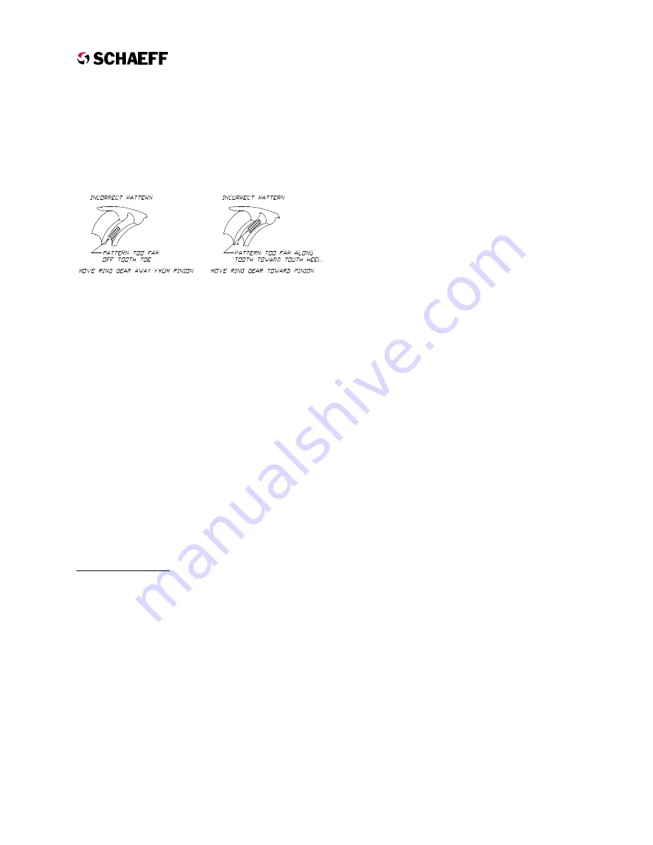
pattern and the tooth toe that is not in contact
with the gear set. To correct for this condition,
remove the carrier from the gear housing, add
additional shims, reassemble and test again.
The illustration to the right however shows the
pattern moving too far along the tooth toward
the tooth heel. To correct for this condition,
remove the carrier, remove some shims,
reassemble and test again.
8.
Once gear teeth pattern conditions are met,
remove carrier from gear housing and set the
shim package aside. Apply a thin coat of
suitable gasket compound to mounting
surfaces of the carrier and housing then
replace shim package. Reattach carrier to
housing using the six bolts supplied with the
gearbox and a thread locking compound.
Torque to 40 lb-ft.
9.
Using grease gun containing Mobilith SHC
220 grease, ensure the cone bearing on gear
shaft is greased.
10. Ensure motor terminal lugs are tight.
11. Reinstall drive unit into the truck.
Carrier Rebuild
Carrier Disassembly
NOTE
The bearings on the drive shaft are pressed on
with an interference fit. Disassembly is
recommended only when one of the carrier's
bearings or seals need to be replaced or the
carrier has excessive endplay (greater than
0.002"). Refer to DRIVE UNIT REBUILD -
DISASSEMBLY for disassembly of the drive
unit.
1.
Place the carrier assembly with the spiral
bevel gear facing up.
2.
Remove the three cap screws (Fig. 2.6, Item
19) securing the bevel gear to the pinion
shaft.
3.
Remove the cap (Fig. 2.6, Item 20) and any
shims underneath.
4.
Lift the spiral bevel gear off of the pinion
shaft.
5.
Slide the pinion shaft out of the carrier
housing.
6.
Remove bearings, bearing cups, and seals as
necessary, being careful not to damage gear
teeth or machined surfaces.
Carrier Assembly
1.
Ensure castings and machined surfaces are
clean and free of foreign material. Clean only
with a rag and mild non-abrasive solvents.
2.
Stand carrier housing on end with large
mounting flange down.
3.
Lubricate the outside diameter of the seals
(Fig. 2.6, Item 27), and carefully press into the
housing individually. Ensure that the lip of the
first seal is downward . Ensure that the lip of
the second seal is pointing upward.
4.
Lubricate outside diameter of the bearing cup
(Fig. 2.6, Item 28), and press evenly into the
carrier housing until properly seated against
the stop.
5.
Turn the carrier housing over so that the large
flange is pointing up. Lubricate bearing cup
(Fig. 2.6, Item 24), and press evenly into the
carrier housing until properly seated against
the stop.
6.
Pack the cone roller bearing (Fig. 2.6, Item
29) with Mobilith SHC 220 grease, or
equivalent. Stand the pinion shaft on end with
the spur gear down. Lubricate the inside
diameter of the packed cone roller bearing
and press evenly onto pinion shaft as shown
until properly seated against the spur gear.
7.
Place the bevel gear face down with support
under the center section opposite the bearing
seat preventing the gear teeth from being
damaged (see Fig. 2.12). Lubricate the inside
diameter of the cone roller bearing (Fig. 2.6,
Item 23) and press onto the bevel gear as
shown until properly seated against the stop.
This bearing should not be packed with heavy
grease. It will eventually be lubricated by
gearbox oil in the gear housing.
E
lectric
C
ounterbalance
H
igh
O
utput
Drive
12/20/99
2.11
Example 3


